Check patentability & draft patents in minutes with Patsnap Eureka AI!

Method for checking a pressure sensor of a fuel storage device

A pressure sensor, fuel storage technology, applied in measuring devices, measuring fluid pressure, fuel injection control, etc., can solve problems such as customer satisfaction impact, and achieve the effect of simplified analysis

Active Publication Date: 2014-10-29
VTESCO TECH GMBH
View PDF5 Cites 0 Cited by
  • Summary
  • Abstract
  • Description
  • Claims
  • Application Information

AI Technical Summary

Problems solved by technology

negatively impact customer satisfaction

Method used


Image

  • Method for checking a pressure sensor of a fuel storage device
  • Method for checking a pressure sensor of a fuel storage device
  • Method for checking a pressure sensor of a fuel storage device

Examples


Embodiment Construction

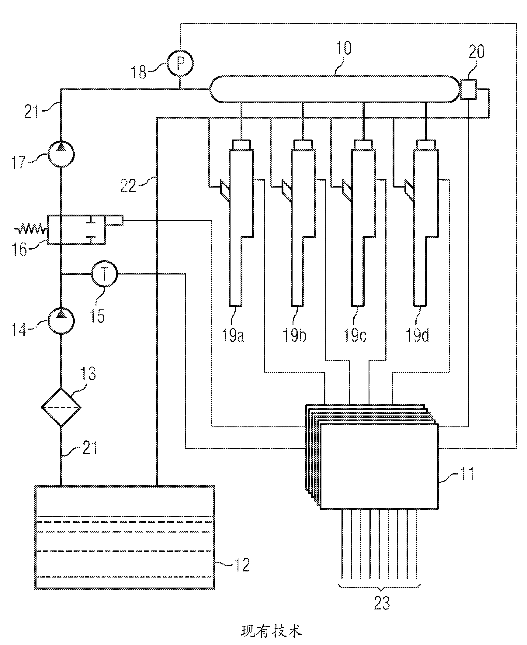
[0024] figure 1 The fuel supply to the internal combustion engine is shown schematically. Here, the fuel is carried in the storage tank 12 of the vehicle. From there, the fuel is sucked in by the low-pressure pump via the fuel filter 13 by means of the delivery line 21 . The quantity supplied to the internal combustion engine in the respective operating state can be influenced by the electromechanical system 11 by means of the regulating valve 16 . The quantity leaving regulating valve 16 is compressed by high-pressure pump 17 and delivered to fuel storage device 10 . In order to measure the pressure flooding in the fuel storage, a pressure measuring device 18 is provided. In this case, the setpoint value of the pressure is determined by the motor control unit 11 as a function of the operating state. If the pressure determined by the sensor 18 is below the target value, the throughput regulator 16 and the high-pressure pump 17 deliver additional fuel to the storage device ...


PUM


Abstract

In a method for testing a pressure sensor of a fuel accumulator device in an internal combustion engine, the pressure in the fuel accumulator device is altered using a first actuating variable. The influence of that alteration on the torque generated by the internal combustion engine is determined by a closed loop control system adjusting a second actuating variable to counteract the effect of the first on the torque output by the internal combustion engine. A deviation of the measured alteration from the expected alteration is then calculated.

Description

technical field [0001] The invention relates to a method for checking a pressure sensor of a fuel storage device of an internal combustion engine. Background technique [0002] Methods and devices for supplying fuel to internal combustion engines are known from the prior art, in which the fuel is conveyed under elevated pressure by means of a pump into a fuel storage device. By means of the injectors assigned to the respective cylinders of the internal combustion engine, fuel is withdrawn from the fuel storage device and supplied to the respective cylinders of the internal combustion engine in a predeterminable amount at a predeterminable time. In this case, the supplied fuel quantity can be adapted to the different operating states via the opening times of the injectors, the number of individual injections and the fuel pressure in the fuel storage. [0003] The fuel pressure in the fuel storage device can be adjusted to an operating state-dependent target value by means of...

Claims


Application Information

Patent Timeline
Patent Type & Authority Patents(China)
IPC IPC(8): F02D41/14F02D41/22F02D41/38G01L27/00
CPCF02D41/3836F02D41/222F02D2041/223Y02T10/40F02D41/1497F02D41/08F02D2200/0602G01L27/007
Inventor C-E.霍夫迈斯特M.克斯鲍尔M.斯坦普费尔
Owner VTESCO TECH GMBH
Features
  • R&D
  • Intellectual Property
  • Life Sciences
  • Materials
  • Tech Scout
  • Unparalleled Data Quality
  • Higher Quality Content
  • 60% Fewer Hallucinations
Learn More