Novel method and equipment for separating volatilizable material from material by continuous vacuum drying

A vacuum drying and volatile technology, which is applied in the direction of drying solid materials and method combinations to dry solid materials, drying chambers/containers, etc., can solve the problems of large heat loss, increased energy consumption, inconvenient entry and exit of material loading and unloading personnel, etc. Ease of entry and exit, increased heat exposure, faster migration and evaporation effects

Inactive Publication Date: 2011-05-04
蔡贵良
View PDF9 Cites 5 Cited by
  • Summary
  • Abstract
  • Description
  • Claims
  • Application Information

AI Technical Summary

Problems solved by technology

[0007] (1) Common materials such as wooden pads are used for the pads or pads where the materials are stacked, which has low thermal conductivity, slow heating of materials, long drying time, and high energy consumption
[0008] (2) The backing plate of the hot plate vacuum drying equipment is physically connected to the heater, the connector is easily damaged, and there are specification restrictions and requirements for the material to be dried, the material loading and unloading rate is low, and material loading and unloading and personnel access are inconvenient
[0010] (4) There is no reasonable design of stru

Method used


Image

  • Novel method and equipment for separating volatilizable material from material by continuous vacuum drying
  • Novel method and equipment for separating volatilizable material from material by continuous vacuum drying
  • Novel method and equipment for separating volatilizable material from material by continuous vacuum drying

Examples


Example Embodiment

[0064] Embodiments of the present invention will be described in detail below with reference to the accompanying drawings.

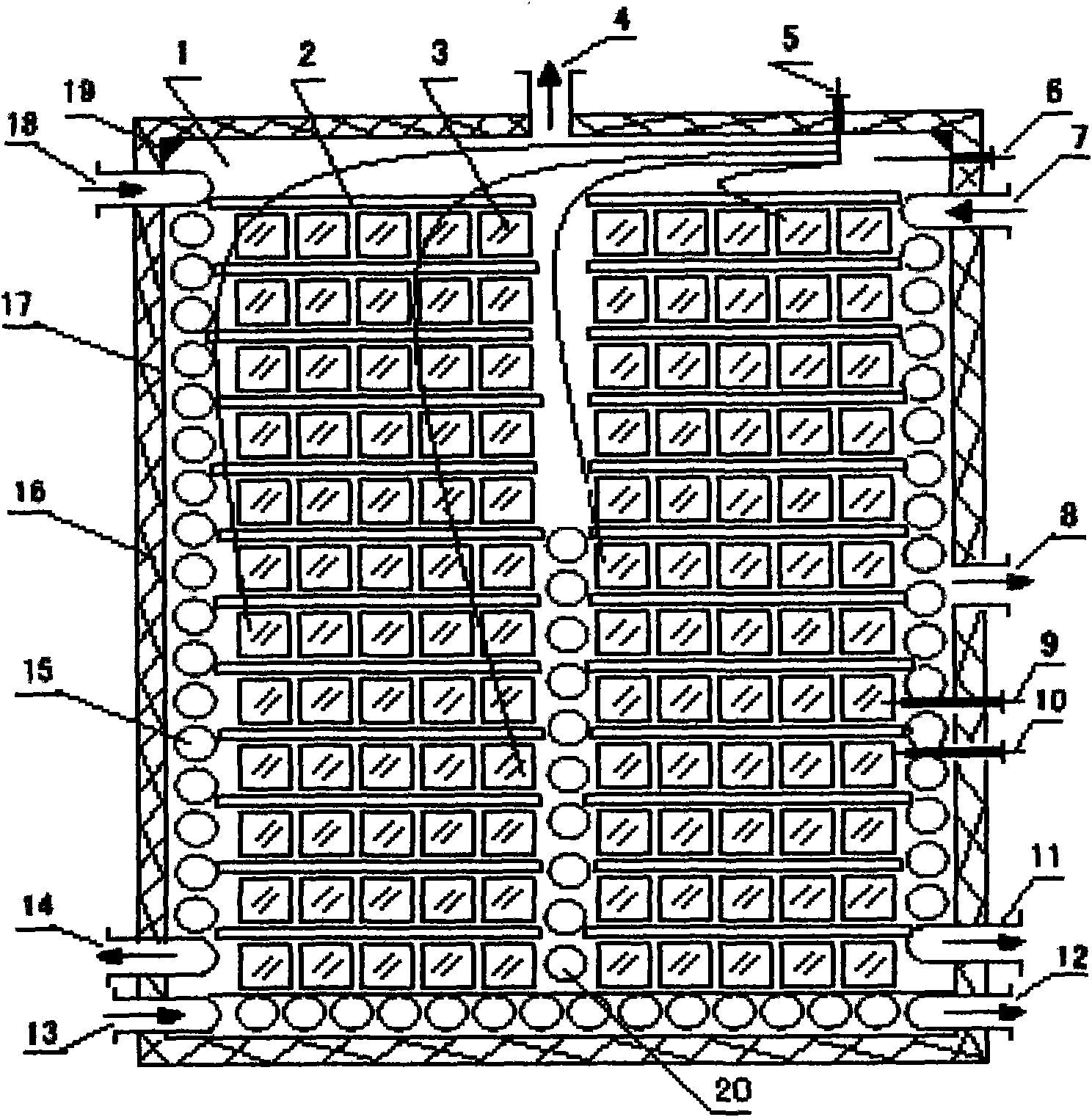
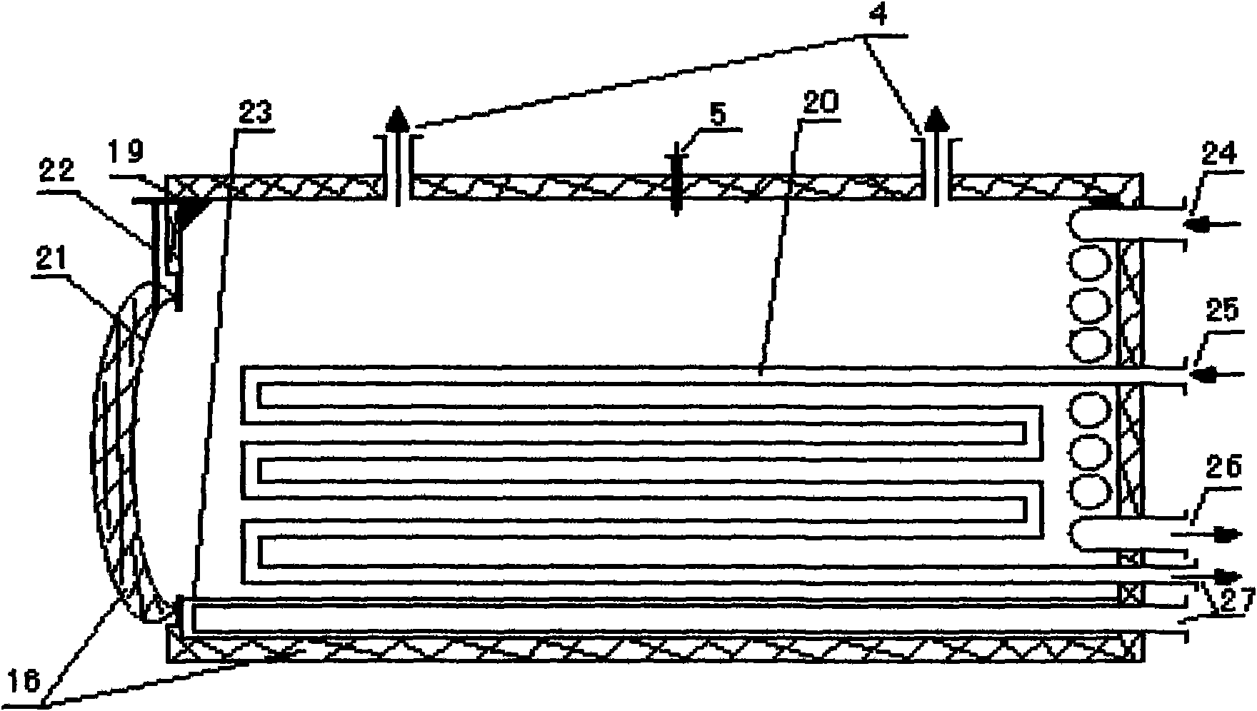
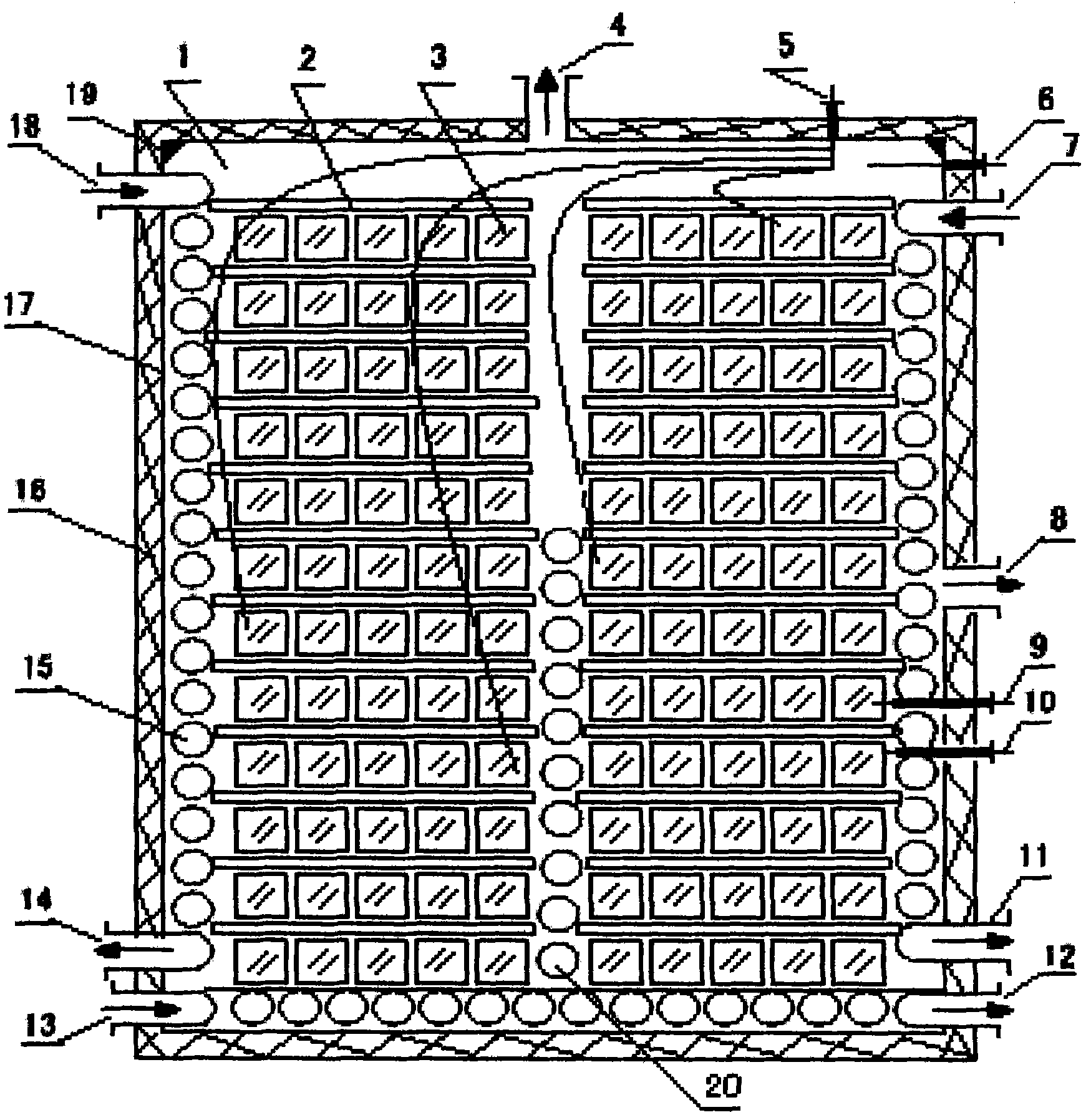
[0065] The schematic diagram of a specific embodiment of the equipment for the novel continuous vacuum drying that detaches material volatiles proposed by the present invention is shown in figure 1 and figure 2 .

[0066] figure 1 A schematic cross-sectional view of the box chamber loaded with materials and gaskets, as shown in the figure: a cube-shaped box chamber 1 is placed between the gasket 2 and the material 3 layers; the top wall of the box has a vacuum port 4, and the side wall has a Vacuum port 8; the top wall of the box body has a probe cable interface 5 for the volatile matter content parameter tester in the material; the side wall of the box body has a chamber 1 internal environment temperature parameter measurement instrument probe interface 6, and material internal temperature parameter measurement Instrument probe interface 9, instru...


PUM


Abstract

The invention provides a novel method and equipment for separating a volatilizable material from a material by continuous vacuum drying. The invention is characterized in that a plurality of cushion strips or a plurality of cushion plates are stacked among a plurality of material layers which are made from a plurality of metal stripes or a plurality of metal plates with high thermal conductivity to be tightly contacted with a heater; the cushion strips or cushion plates are in a hollow or solid structure, and the end sockets of the cushion strips or cushion plates are provided with seal plates or provided with no seal plates so as not to be mutually and fixedly connected with the heater and other components in a material box and be capable of willfully and freely moving; the box is internally and reasonably provided with the heater; the box is internally provided with a structure strengthening piece; the material is preheated to a stated temperature, preserved and balanced for a stated time, and vacuumized, and the vacuumizing speed is controlled, so that the material is continuously dried to separate out the volatilizable material in the continuous vacuum environment; and after each technological parameter is up to the standard, the heating and the vacuumizing are stopped, so that the temperature of the material is preserved and balanced for a stated time under the condition. The invention has the advantage of being short in drying time, high in efficiency, low in energy consumption, simple in technology, good in drying quality, large in the volume of equipment, convenient to load the material, large in loading quantity, low in running cost, and is insecticidal, mildewproof, defatted and peculiar smell-removed.

Description

technical field [0001] The invention relates to a method and equipment for continuous vacuum drying to remove volatile matter from materials. Background technique [0002] Before the material is made into a finished product, it must usually be dried to remove the volatile matter in the material, so as to prevent the finished product from cracking, deformation, mildew, insect growth and odor during use. [0003] The conventional method of drying and removing the volatile matter of the material is to place the material in a chamber, and dry and remove the volatile matter of the material under a heating environment. In conventional drying, heat is transferred to the surface of the material through conduction, convection, and radiation, and then the heat is transferred to the interior of the material by conduction. When the inside of the material rises to a certain temperature, the volatile matter will migrate from the inside to the surface of the material and be evaporated and...

Claims


Application Information

Patent Timeline
IPC IPC(8): F26B9/06F26B7/00F26B23/00F26B25/12
Inventor 蔡贵良
Owner 蔡贵良
Why Eureka
Try Eureka