Implementation method and device of point-to-multipoint pseudowire protective network
An implementation method and network technology, applied in the field of communication, to achieve the effect of improving stability and security
- Summary
- Abstract
- Description
- Claims
- Application Information
AI Technical Summary
Problems solved by technology
Method used
Image

Examples
example 1
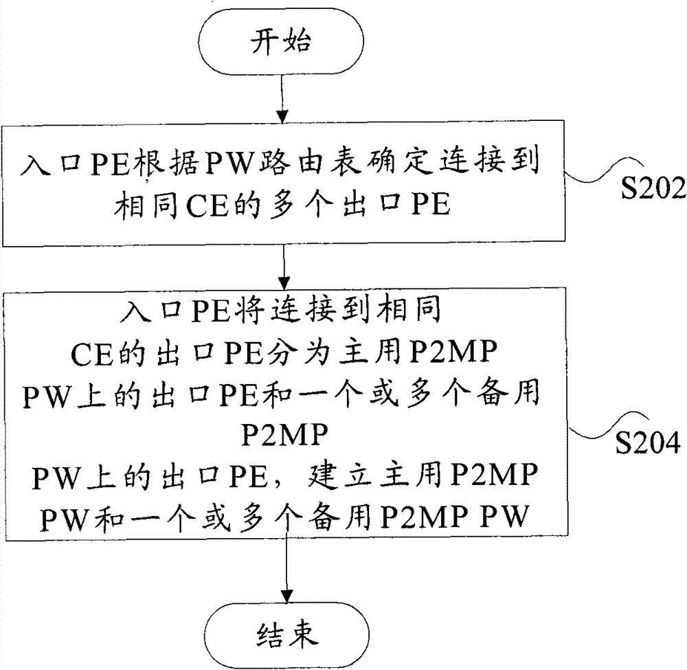
[0089] The ingress PE determines the egress PE connected to the same CE, and divides these PEs into the egress PE on the active P2MP PW and the egress PE on the standby P2MP PW, and establishes the active P2MP PW and the standby P2MP PW respectively according to the above grouping.
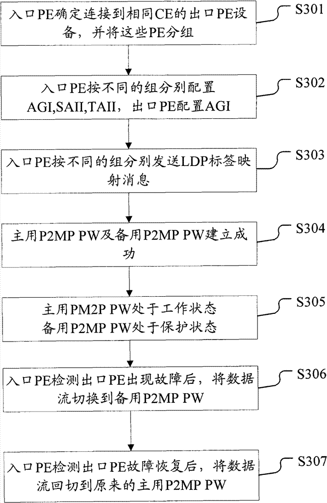
[0090] Image 6 It is a flow chart of a method for implementing egress PE protection of a P2MP PW in Example 1 according to an embodiment of the present invention, as shown in Image 6 As shown, the method includes the following steps S601 to S607:
[0091] In step S601, the ingress PE is configured with AII; the egress PE connected to the same CE is configured with the same AII.
[0092] for Figure 4 In the protection network shown, PE1 is the ingress PE, and the carrier edge devices PE2, PE3, PE4, and PE5 are egress PEs. AII11 is configured on PE1, AII21 is configured on PE4 and PE2, and AII31 is configured on PE3 and PE5.
[0093] In step S602, AII information is advertised through protocol...
example 2
[0107] After the active and standby P2MP PWs are established, when the active P2MP PW fails, the data flow is switched to the standby P2MP PW.
[0108] Figure 7 It is a flow chart of the realization method of the egress PE protection of the P2MP PW in Example 2 according to the embodiment of the present invention, as shown in Figure 7 As shown, the method includes the following steps S701 to S702:
[0109] In step S701, the ingress PE detects that the egress PE of the active P2MP PW fails.
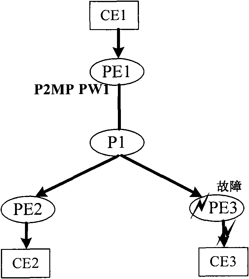
[0110] Figure 5 is a schematic diagram of failure of the primary P2MP PW egress PE according to an embodiment of the present invention, for Figure 5 In the protection network shown in the figure, PE1 can detect that PE2 or PE3 is faulty through P2MP BFD.
[0111] In step S702, the data flow is switched to the standby P2MP PW, and the active P2MP PW no longer forwards the data flow.
[0112] for Figure 5 In the protection network shown in the figure, when PE1 detects a fault in e...
example 3
[0114] When the failure of the active P2MP PW recovers, the data flow is switched to the original active P2MP PW.
[0115] Figure 8 It is a flow chart of the realization method of the egress PE protection of the P2MP PW in Example 3 according to the embodiment of the present invention, as shown in Figure 8 As shown, the method includes the following steps S801 to S802:
[0116] In step S801, the ingress PE detects that the failure of the egress PE of the active P2MP PW is recovered.
[0117] E.g, Figure 4 The shown P2MP PW egress PE protection network can also be regarded as a schematic diagram after the active P2MP PW egress PE fails and recovers. PE1 can detect the fault recovery of PE2 and PE3 through P2MP BFD.
[0118] In step S802, the data flow is switched back to the original active P2MP PW, and the standby P2MP PW no longer forwards the data flow.
[0119] E.g, Figure 4 The shown P2MP PW egress PE protection network can also be regarded as a schematic diagram...
PUM
 Abstract
Description
Claims
Application Information
 - R&D
- Intellectual Property
- Life Sciences
- Materials
- Tech Scout
- Unparalleled Data Quality
- Higher Quality Content
- 60% Fewer Hallucinations
Browse by: Latest US Patents, China's latest patents, Technical Efficacy Thesaurus, Application Domain, Technology Topic, Popular Technical Reports.
© 2025 PatSnap. All rights reserved.Legal|Privacy policy|Modern Slavery Act Transparency Statement|Sitemap|About US| Contact US: help@patsnap.com