
Heat exchanger structure and assembly method thereof

An assembly method and heat exchanger technology, applied in heat exchange equipment, evaporator/condenser, lighting and heating equipment, etc., to achieve the effects of easy assembly, avoiding brazing, and saving welding materials

Inactive Publication Date: 2011-05-18
LG ELECTRONICS (TIANJIN) APPLIANCES CO LTD
View PDF5 Cites 14 Cited by
  • Summary
  • Abstract
  • Description
  • Claims
  • Application Information

AI Technical Summary

Problems solved by technology

[0007] The technical problem to be solved by the present invention is to overcome the shortcomings of the above-mentioned finned tube condenser and provide a heat exchanger structure that is easy to install and has a high heat dissipation coefficient.

Method used


Image

  • Heat exchanger structure and assembly method thereof
  • Heat exchanger structure and assembly method thereof
  • Heat exchanger structure and assembly method thereof

Examples


Embodiment Construction

[0025] The structure of the heat exchanger of the present invention will be further described below with reference to the accompanying drawings.

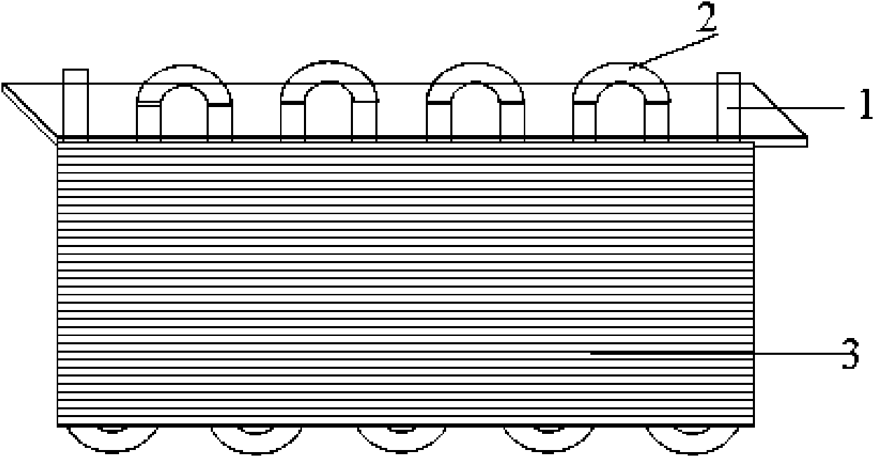
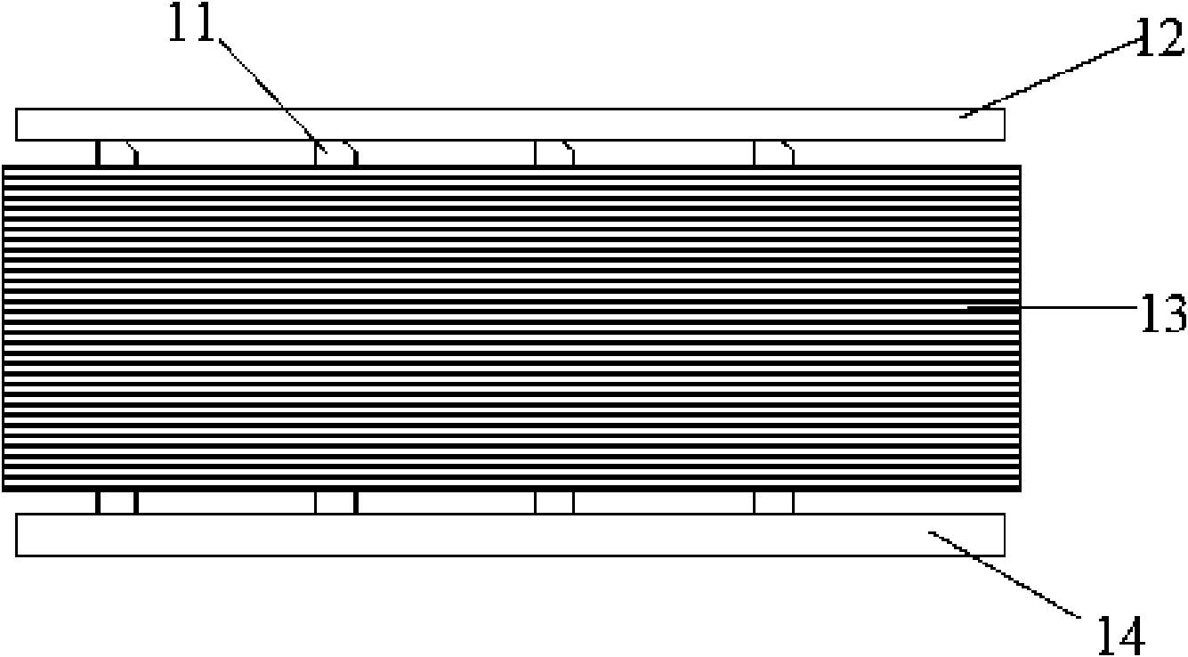
[0026] figure 2 As shown, the heat exchanger structure of the present invention includes an inlet header 12, an outlet header 14, fins 13 that are tightly stacked between the inlet header 12 and the outlet header 14, and through the fins 13 the inlet header 12 and the flat tube 11 connected to the outlet header 14, the flat tube is generally an aluminum flat tube, its cross section is a rounded rectangular structure, and a plurality of partition plates are arranged in the lumen, and the partition plates are arranged along the flat The tube extends in the pipeline direction and evenly divides the lumen into several microchannels that are not connected to each other; it also includes gaskets that are sleeved on the flat tube and arranged on both sides of the fins 13 .

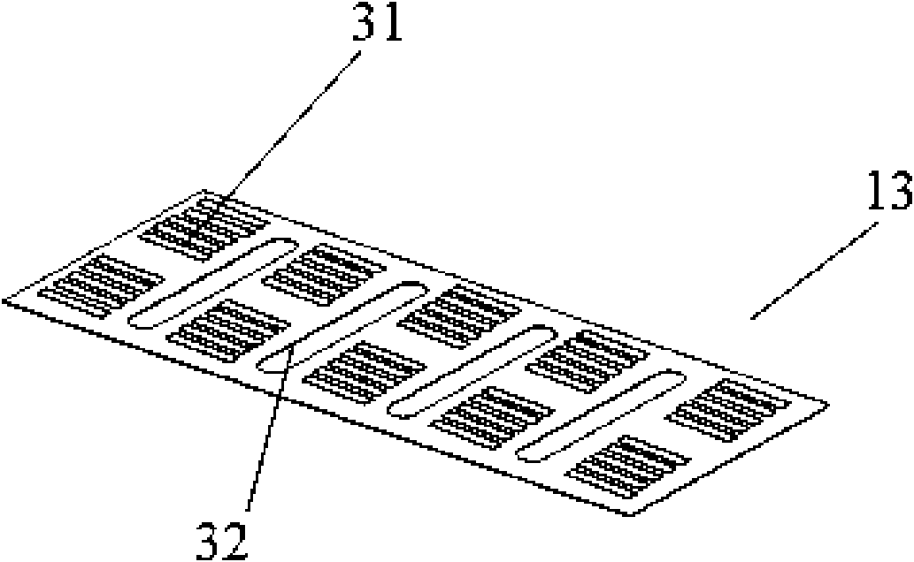
[0027] image 3 Shown is the structure of the fin 13 of the pr...


PUM


Abstract

The invention discloses a heat exchanger structure, which comprises an inlet collecting pipe, an outlet collecting pipe, fins, a flat pipe and gaskets, wherein the fins are provided with pipeline grooves, and the inside diameter of the gaskets is smaller than the thickness of the flat pipe. The invention also discloses an assembly method for the heat exchanger structure, which comprises the following steps of: (1) heating the gasket; (2) correspondingly arranging the fins and the gaskets on a bearing table layer by layer; (3) sequentially inserting the flat pipe into the fins and the gaskets so that the flat pipe can pass through the radiating gaskets to form clearance fit; (4) pushing a pressing table by using pressing equipment to press the fins and the gaskets so that the fins and the gaskets are tightly jointed; and (5) keeping constant pressure, blowing cool air to the gaskets, and cooling the gaskets to normal temperature so that the gaskets and the flat pipe form clearance fit and fixed connection of the fins and the flat pipe is completed. The structure is easy to assemble; the contact area of the fins and the radiating gaskets is original four times, so the radiating efficiency of a radiator is promoted; and due to a fixed mode, soldering is avoided, a solder is saved, and the cost is reduced.

Description

technical field [0001] The invention relates to a condenser, in particular to a heat exchanger structure and an assembly method thereof. Background technique [0002] When the room air conditioner is running in cooling mode, the indoor air flows through the evaporator to reduce the temperature. At the same time, because the temperature of the surface of the evaporator is generally significantly lower than the dew point temperature of the air, when the air flows through the surface of the evaporator, part of the moisture in the air will be precipitated, thereby forming condensed water on the surface of the evaporator. Condensed water on the surface of the evaporator should be drained in time. If the condensed water accumulates on the surface of the evaporator, it will block the air passage, increase the flow resistance of the air, and reduce the efficiency of the evaporator: water droplets may also be blown into the room, resulting in unqualified quality of the air condition...

Claims


Application Information

Patent Timeline
IPC IPC(8): F25B39/04F28F1/30B21D53/08
Inventor 车金峰崔静
Owner LG ELECTRONICS (TIANJIN) APPLIANCES CO LTD
Features
  • Generate Ideas
  • Intellectual Property
  • Life Sciences
  • Materials
  • Tech Scout
  • Unparalleled Data Quality
  • Higher Quality Content
  • 60% Fewer Hallucinations
Learn More