
Transmission line driver and driving method

A driving method and transmission line technology, applied in the field of drivers, can solve the problems of unreachable circuits and high cost.

Active Publication Date: 2011-05-18
REALTEK SEMICON CORP
View PDF3 Cites 4 Cited by
  • Summary
  • Abstract
  • Description
  • Claims
  • Application Information

AI Technical Summary

Problems solved by technology

Although it can solve the problem of impedance matching and output fixing, however, it will create a problem of high cost
In addition, in actual manufacturing, it is impossible to achieve a 100% ideal circuit. Therefore, how to obtain the best solution in terms of cost performance, that is, to meet the requirements of product quality and manufacture at the lowest cost, has become a transmission line driver design. main considerations on

Method used


Image

  • Transmission line driver and driving method
  • Transmission line driver and driving method
  • Transmission line driver and driving method

Examples


Embodiment Construction

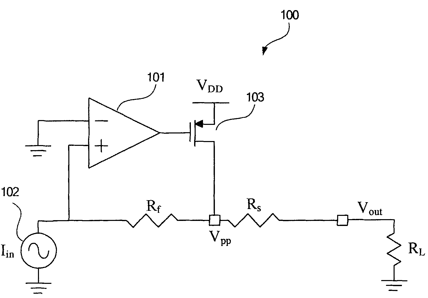
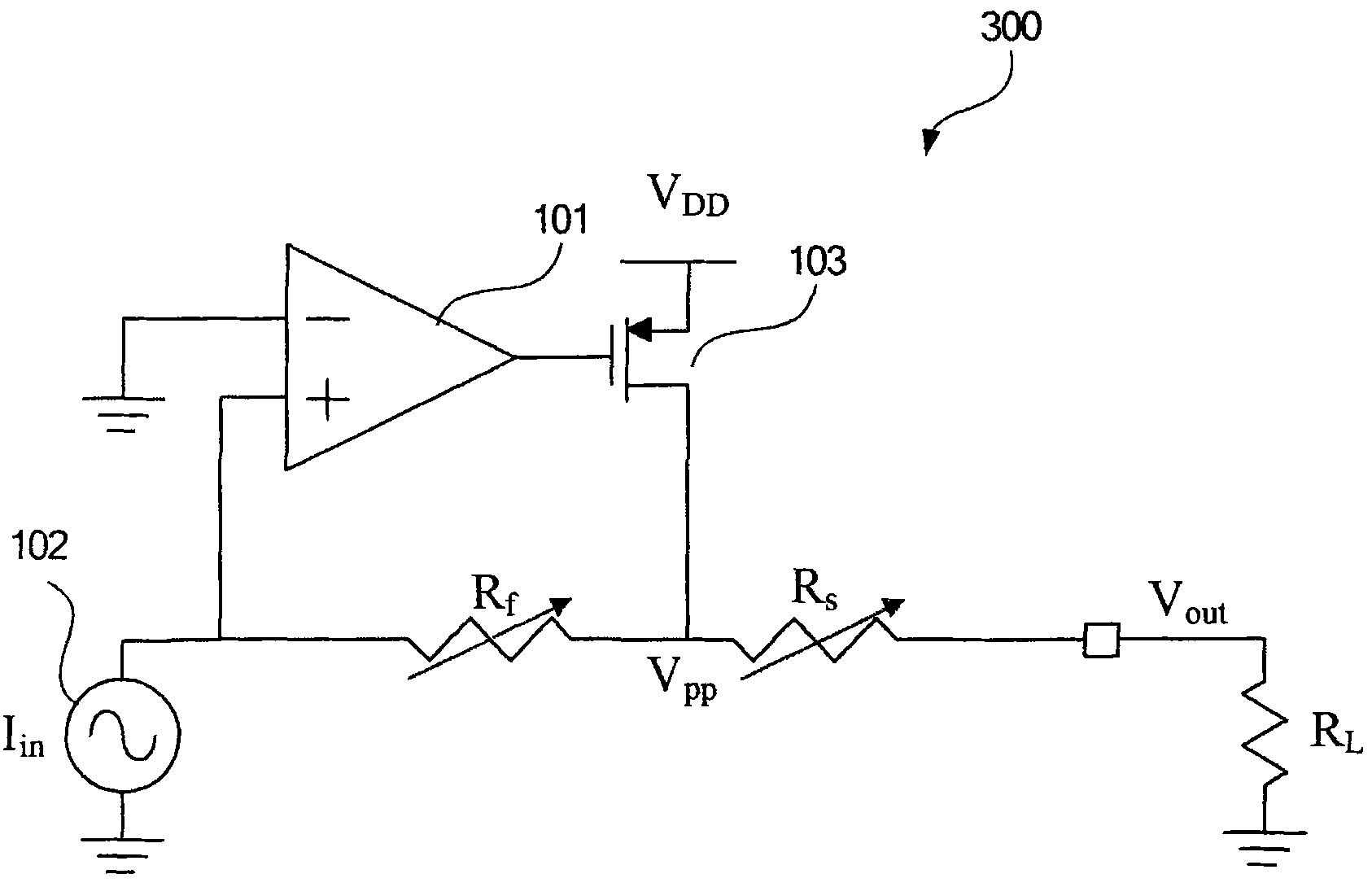
[0029] The present invention achieves the purpose of stabilizing the output voltage by providing a mixed current source as the input current source. where the mixed current source I mix Contains two parts: 1. Internal current source (i b ); 2. External current source (i bx ). where the internal current source (i b ) is generated by the bandgap voltage (Bandgap voltage) and the internal reference resistance, while the external current source (i bx ), which is generated by the bandgap voltage and the external reference resistance. The internal reference resistance is the internal resistance parameter when the IC is manufactured, while the external reference resistance is the resistance parameter of the external components of the IC. The internal current source is the current source (i b ), while the external current source (i bx ) is formed by the IC external resistors. After the two current sources are mixed, the purpose of the present invention can be achieved.

[003...


PUM


Abstract

The invention relates to a transmission line driver and a driving method. In the invention, a mixed current source is used as an input current source to ensure constant output voltage, wherein the mixed current source comprises an internal current source and an external current source. The mixed current source is supplied to a single-ended transmission line driver or a differential type transmission line driver so as to output voltage constantly.

Description

technical field [0001] The present invention relates to a driver, in particular to a transmission line driver and a driving method. Background technique [0002] The general transmission line driver (Line driver) is a voltage buffer, which uses the output current to drive the load resistance, and the resistance value of the impedance matching will vary due to the length of the driven cable, the working environment or other external factors. . In addition, the transmission line driver must maintain a larger output voltage (output swing), higher linearity (linearity), better power efficiency (power efficiency) and impedance matching of the transmission line, etc. to achieve the purpose of effective driving. [0003] There are two traditional transmission line drive methods: voltage source drive and current source drive. Among them, the technology of current source driving is to use the current signal to drive the load impedance R of the transmission line L , to produce a su...

Claims


Application Information

Patent Timeline
IPC IPC(8): H04L25/02H03F3/50H03F3/45
Inventor 廖书谅
Owner REALTEK SEMICON CORP
Learn More