Check patentability & draft patents in minutes with Patsnap Eureka AI!

Method of supplying liquid crystal to liquid crystal coater

A liquid crystal coating machine, liquid crystal technology, applied to the surface coating liquid device, coating, optics, etc., can solve the problem of long time consumption

Active Publication Date: 2016-05-11
TOP ENG CO LTD
View PDF6 Cites 0 Cited by
  • Summary
  • Abstract
  • Description
  • Claims
  • Application Information

AI Technical Summary

Problems solved by technology

Therefore, since the liquid crystal is supplied to the liquid crystal bottle 530 during the process of applying a predetermined amount of liquid crystal to the substrate, it takes a long time to apply the predetermined amount of liquid crystal to the substrate.

Method used


Image

  • Method of supplying liquid crystal to liquid crystal coater
  • Method of supplying liquid crystal to liquid crystal coater
  • Method of supplying liquid crystal to liquid crystal coater

Examples


Embodiment Construction

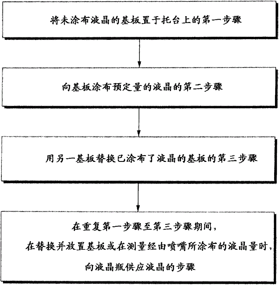
[0048] A method for supplying liquid crystals to a liquid crystal coating machine according to an embodiment of the present invention will be described in detail below with reference to the accompanying drawings.

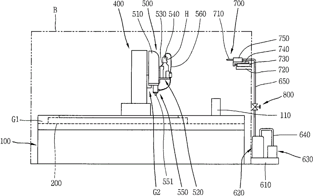
[0049] First combine the figure 1 The liquid crystal coater and the liquid crystal supply unit will be described.

[0050] A liquid crystal coater is installed, and then a clean booth B is installed to cover the liquid crystal coater. The liquid crystal supply unit is installed outside the clean room B.

[0051] The liquid crystal coating machine comprises: a main frame 100; a pallet 200, which is installed on the main frame 100; a first guide unit G1, which is connected to the main frame 100 in a manner located on both sides of the pallet 200; a coating head unit Support frame 400, it is coupled with the first guide unit G1; The first drive unit (not shown), its effect is to move coating head unit support frame 400; The second guide unit G2, it is arranged on coa...


PUM


Abstract

The invention discloses a method for supplying liquid crystal to a liquid crystal coater. The method comprises the steps of (a) placing a substrate uncoated with liquid crystals on a support bench, (b) coating predetermined amount of liquid crystals onto the substrate through a coater head unit having a liquid crystal bottle with liquid crystal stored therein, and (c) replacing the substrate coated with predetermined amount of liquid crystals with a substrate uncoated with liquid crystals, repeating steps (a) to (c) and supplying liquid crystal to the liquid crystal bottle at the step (a) or step (c).

Description

technical field [0001] The present invention relates to a method of supplying liquid crystals to a liquid crystal coater. Background technique [0002] figure 1 It is a side view schematically showing a liquid crystal coater and a liquid crystal supply unit. [0003] Such as figure 1 As shown, a liquid crystal coater is installed, and then a clean booth B is installed to cover the liquid crystal coater. The liquid crystal supply unit is installed outside the clean room B. [0004] The liquid crystal coating machine comprises: a main frame 100; a pallet 200, which is installed on the main frame 100; a first guide unit G1, which is connected to the main frame 100 in a manner located on both sides of the pallet 200; a coating head unit Support frame 400, it is coupled with the first guide unit G1; The first drive unit (not shown), its effect is to move coating head unit support frame 400; The second guide unit G2, it is arranged on coating head unit On the supporting frame...

Claims


Application Information

Patent Timeline
Patent Type & Authority Patents(China)
IPC IPC(8): B05C5/00B05C11/10B05C11/115G02F1/1341
Inventor 申承炫
Owner TOP ENG CO LTD
Features
  • R&D
  • Intellectual Property
  • Life Sciences
  • Materials
  • Tech Scout
  • Unparalleled Data Quality
  • Higher Quality Content
  • 60% Fewer Hallucinations
Learn More