Check patentability & draft patents in minutes with Patsnap Eureka AI!

Screw mounting device

An installation device and screw technology, applied in metal processing, metal processing equipment, manufacturing tools, etc., can solve the problems of affecting production efficiency, inconvenient operation, easy to fall, etc., and achieve the effect of convenient production and simple structure

Inactive Publication Date: 2012-08-29
天津中环新宇科技有限公司
View PDF6 Cites 0 Cited by
  • Summary
  • Abstract
  • Description
  • Claims
  • Application Information

AI Technical Summary

Problems solved by technology

However, this operation is extremely inconvenient for some special installation requirements. For example, when installing screws inside a part with a small space, it is easy to drop when it is not easy to hold by hand, which greatly affects production efficiency.

Method used


Image

  • Screw mounting device
  • Screw mounting device
  • Screw mounting device

Examples


Embodiment Construction

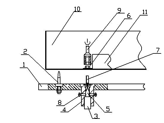
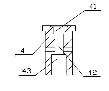
[0009] Such as figure 1 , 2 As shown, the screw installation device includes a base plate 1, a positioning nail 2, a strong magnetic steel 3, a fixing column 4, and a screwdriver 5, and a plurality of fixing columns 4 are arranged at the bottom of the base plate 1; the upper part of the fixing column 4 is provided with a cavity 41, and the center There is a through hole 42, and the lower part is provided with a blind hole 43; the screwdriver 5 is placed in the through hole 42, fixed with a screw 8 from both sides, and the strong magnetic steel 3 is placed in the blind hole 43; Locating nail 2, fixed with nuts;

[0010] The cross-sectional diameter of the cavity 41 is slightly larger than the diameter of the screw cap, and the axial height of the cavity 41 is equal to the height of the screw cap, so that the screw cap is completely sunk in the cavity 41. The screw cap is placed in the cavity 41 .

[0011] The diameter of the blind hole 43 is greater than the diameter of the ...


PUM


Abstract

The invention relates to a screw mounting device which comprises a baseplate, positioning nails, strong magnet steel, fixed columns and screw drivers, wherein the lower part of the baseplate is provided with a plurality of fixed columns; the upper part of each fixed column is provided with a cavity, the central part of each fixed column is provided with a through hole, and the lower part of each fixed column is provided with a blind hole; each screw driver is arranged in each through hole, and fixed by screws from the two sides of each fixed column; the strong magnet steel is arranged in eachblind hole; and the upper part of the baseplate is provided with two positioning nails fixed by nuts. The screw mounting device provided by the invention has the advantages that the strong magnet steel conducts the magnetism to the screws by magnetic-conductive screw drivers, so that the screws can be automatically led into screw holes so as to adsorb and fix the screws; and meanwhile, the screw mounting device provided by the invention is simple in structure, and in the mounting process, all screws can be put together once and then directly fixed together, therefore, the screw mounting device is very convenient to produce and is practical.

Description

technical field [0001] The invention relates to the technical field of household appliances, in particular to a magnetic alloy steel screw mounting device. Background technique [0002] The screws used in daily production are mainly alloy steel screws with magnetism. When installing, this kind of screws can be adsorbed on the screw bit, which is convenient for installation. However, this operation is extremely inconvenient when some special installation requirements are required. For example, installing screws inside a part with a small space is easy to drop when it is not easy to hold by hand, which greatly affects production efficiency. Contents of the invention [0003] The object of the present invention is to overcome the disadvantages of the above-mentioned prior art, and provide an auxiliary installation structure for installing magnetic alloy steel screws in a small space. [0004] The technical solution adopted by the present invention in order to achieve the abo...

Claims


Application Information

Patent Timeline
Patent Type & Authority Patents(China)
IPC IPC(8): B23P19/06
Inventor 曹跃何广来丁萍温岩王英刘增勇牛莉
Owner 天津中环新宇科技有限公司
Features
  • R&D
  • Intellectual Property
  • Life Sciences
  • Materials
  • Tech Scout
  • Unparalleled Data Quality
  • Higher Quality Content
  • 60% Fewer Hallucinations
Learn More