Method for depositing film by using LPCVD process
A technology of thin film and deposition process, which is applied in the field of improving the deposition of thin film by LPCVD process, can solve the problems of different total thermal budget, different temperature, different temperature, etc., to improve yield, reduce thermal budget difference, and reduce manufacturing cost effect
- Summary
- Abstract
- Description
- Claims
- Application Information
AI Technical Summary
Problems solved by technology
Method used
Image

Examples
Embodiment 1
[0094] Figure 5 It is a flow chart of the method in Embodiment 1 of the present invention. Figure 6 It is a schematic diagram of the temperature curve in Example 1 of the present invention. combine Figure 5 , Figure 6 As shown, the above step 402 can be realized through the following steps:
[0095] Step 501 , in the loading stage of the crystal boat, the temperature of each temperature zone in the heater of the furnace tube is gradually increased to the same predetermined temperature value.
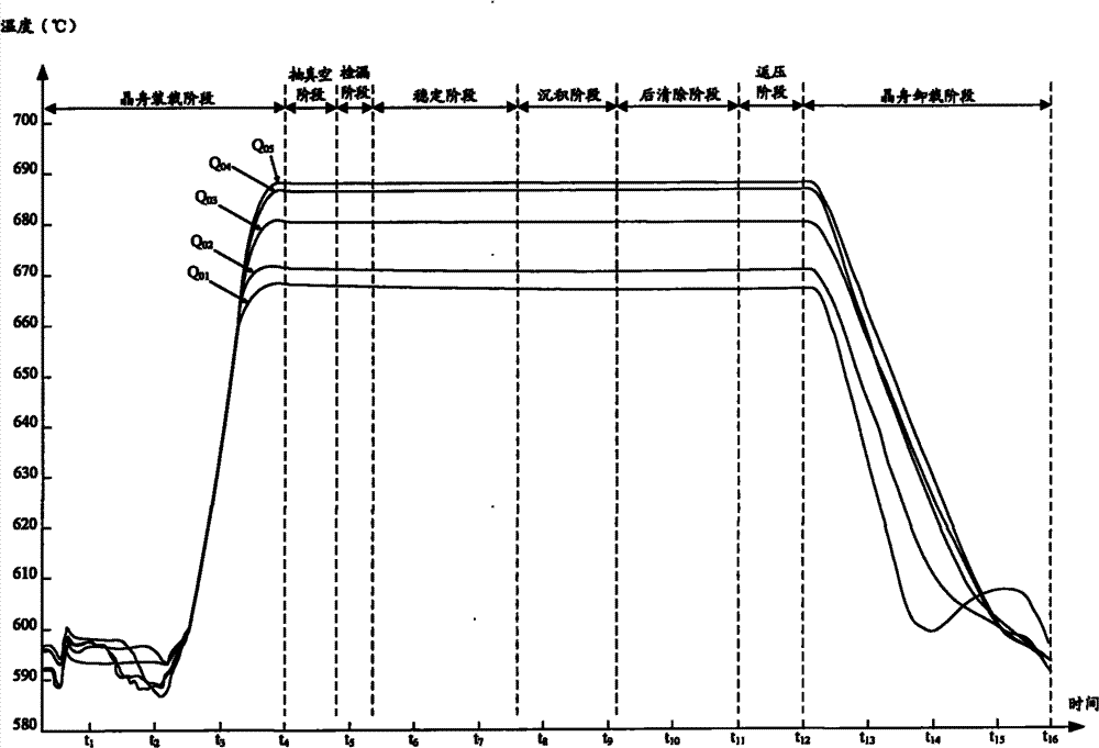
[0096] In the crystal boat loading stage in the prior art, the temperature of each temperature zone in the heater of the furnace tube will gradually increase to different temperature values, such as image 3 shown. Therefore, when the loading phase of the wafer boat is completed, the temperatures of the above-mentioned temperature zones are not the same, and the temperature values of each temperature zone decrease sequentially according to the position of each temperature zone...
Embodiment 2
[0107] Figure 7 It is a flow chart of the method in Embodiment 2 of the present invention. Figure 8 It is a schematic diagram of the temperature curve in Example 2 of the present invention. combine Figure 7 , Figure 8 As shown, the above step 402 can be realized through the following steps:
[0108] Step 701, during the loading stage of the crystal boat, gradually increase the temperature of each temperature zone in the heater of the furnace tube to each preset temperature value, so that the temperature values of each temperature zone increase from the top to the bottom according to the position of each temperature zone. The order to the next increases sequentially.
[0109] In the prior art, when the crystal boat loading phase is completed, the temperature values of the temperature in each temperature zone will decrease sequentially according to the position of each temperature zone from top to bottom, that is, the temperature in the lower temperature zone will be...
Embodiment 3
[0120] Figure 9 It is a flow chart of the method in Embodiment 3 of the present invention. Figure 10 It is a schematic diagram of the temperature curve in Example 3 of the present invention. combine Figure 9 , Figure 10 As shown, the above step 402 can be realized through the following steps:
[0121] Step 901, in the post-cleaning stage, gradually increase the temperature of each temperature zone in the heater of the furnace tube to the same predetermined temperature value.
[0122] Such as image 3 As shown, in the post-cleaning stage in the prior art, the temperature values of each temperature zone in the heater of the furnace tube decrease sequentially according to the position of each temperature zone from top to bottom. For example, the temperature value of the upper temperature zone is greater than the temperature value of the lower temperature zone. Therefore, the wafers loaded in different areas of the boat will not get the same thermal budget at this stag...
PUM
 Abstract
Description
Claims
Application Information
 - R&D
- Intellectual Property
- Life Sciences
- Materials
- Tech Scout
- Unparalleled Data Quality
- Higher Quality Content
- 60% Fewer Hallucinations
Browse by: Latest US Patents, China's latest patents, Technical Efficacy Thesaurus, Application Domain, Technology Topic, Popular Technical Reports.
© 2025 PatSnap. All rights reserved.Legal|Privacy policy|Modern Slavery Act Transparency Statement|Sitemap|About US| Contact US: help@patsnap.com