Supercharge Your Innovation With Domain-Expert AI Agents!

Flexible universal fan blade wheel

A wind impeller, flexible technology, applied in wind turbines at right angles to the wind direction, wind turbines, climate sustainability, etc., can solve high operating noise and loss, difficulty and workload of operation and maintenance, low wind efficiency, etc. problems, to achieve high wind efficiency, operation and maintenance difficulty and workload reduction, and the effect of simple blade structure

Active Publication Date: 2013-03-20
南通同旭贸易有限公司
View PDF0 Cites 0 Cited by
  • Summary
  • Abstract
  • Description
  • Claims
  • Application Information

AI Technical Summary

Problems solved by technology

The existing universal wind impeller is a frame-type unidirectional vertical turbofan structure, which can realize the wind power independent of the wind direction, but its wind power efficiency is very low
The recently developed universal wind impeller is a structure with a large leaf fan and a small movable leaf fan. Although it can realize the wind power function independent of the wind direction and high wind power efficiency, its complex blade structure will make operation and maintenance difficult and difficult. Increased workload, but also high operating noise and wear

Method used


Image

  • Flexible universal fan blade wheel
  • Flexible universal fan blade wheel
  • Flexible universal fan blade wheel

Examples


Embodiment Construction

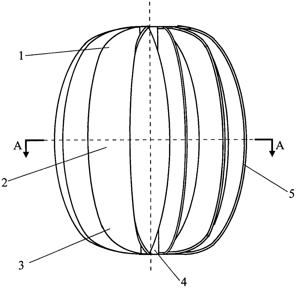
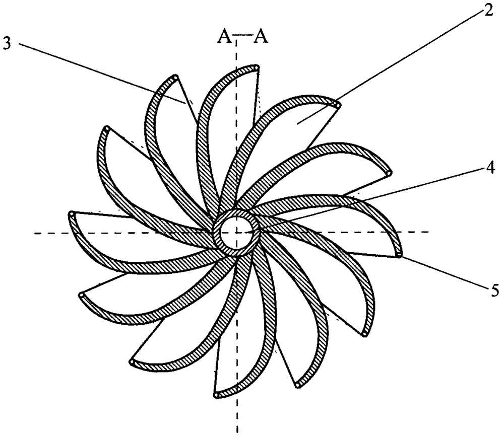
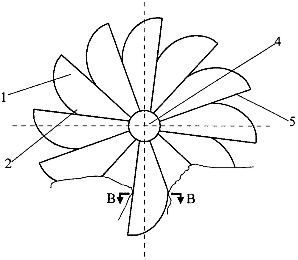
[0015] exist Figure 1 ~ Figure 4 The structure view of the flexible universal wind impeller shown and Figure 5 In the schematic diagram of the flexible blade shown: the universal impeller is mainly composed of several flexible nitrile rubber fan blades, and each fan blade is divided into an upper wind guide blade section 1, a main windward turbine fan blade section 2 and a lower wind guide blade section 3 The three sections, with the windward high wind resistance concave vortex surface and the leeward low wind resistance convex convex surface, constitute the two sides of the curved blade body. The root of each blade is fixed on the side of the column of the rotor-shaft structure 4 according to the tangential direction of the inner concave vortex of the blade, and the angle formed by the line connecting the outer edge 5 of each two blades to the edge of the root is axially made Equal, radially make the connecting line from the midpoint of the upper top edge 5 of each blade t...


PUM


Abstract

The invention discloses a flexible universal fan blade wheel with a compact structure, which can realize wind driving function irrelevant to the wind direction and very high wind power efficiency and ensures that running and maintenance difficulties and the workload are greatly reduced with a simple blade structure. The fan blade wheel consists of a plurality of flexible fan blades which are fixedly connected to a rotor-shaft structure, wherein each flexible fan blade consists of an upper guide fan blade section, a main windward vortex fan blade section and a lower guide fan blade section to form a flexible curved face body with a concave vortex surface and a convex surface; the fan blades are in the same tangential direction of concave vortex surface and are fixedly connected to the post side face of the rotor-shaft structure; included angles between connecting lines of the outer side edges and the inner side edges of every two fan blades in the axial direction are the same as each other; and the connecting line between the upper top point and the lower top point of each fan blade is parallel with an axial lead in the radial direction.

Description

technical field [0001] The invention relates to a wind impeller of a wind power engine. Background technique [0002] At present, the wind impellers of almost all wind turbines or other wind-powered wind impellers are driven in one direction, and their wind efficiency is guaranteed by constantly adjusting the windward or downwind direction, which makes the structure of the wind power engine system complicated, so that additional Set the wind direction follow-up control system. Like this, not only cause cost to raise, but also can make running cost raise, work efficiency reduces. Especially for high-power system wind turbines, even with an excellent wind direction follow-up control system, it is difficult to achieve high-sensitivity follow-up of rapid and frequent wind direction changes. Therefore, it is an urgent problem to be solved urgently to develop a kind of wind-driven engine which has nothing to do with the wind direction. The existing universal wind impeller is a ...

Claims


Application Information

Patent Timeline
Patent Type & Authority Patents(China)
IPC IPC(8): F03D3/06
CPCY02E10/74
Inventor 屈百达朱焯炜
Owner 南通同旭贸易有限公司
Features
  • R&D
  • Intellectual Property
  • Life Sciences
  • Materials
  • Tech Scout
  • Unparalleled Data Quality
  • Higher Quality Content
  • 60% Fewer Hallucinations
Learn More