Supercharge Your Innovation With Domain-Expert AI Agents!

Magnetic lock device

A magnetic lock and lock body technology, which is applied to building locks, non-mechanical transmission-operated locks, buildings, etc., can solve problems such as poor applicability and increased design complexity

Inactive Publication Date: 2013-06-05
STATE GRID CORP OF CHINA +3
View PDF6 Cites 0 Cited by
  • Summary
  • Abstract
  • Description
  • Claims
  • Application Information

AI Technical Summary

Problems solved by technology

Therefore, a certain type of magnetic lock of this kind of magnetic lock cannot be applied to a device whose required magnetic force is different from that of the magnetic lock of this type, and the applicability is poor.
In addition, when lock bodies with different magnetic forces are required, different types of magnets need to be selected to design the magnetic lock so that the magnetic lock can produce different magnetic forces, which increases the complexity of the design

Method used


Image

  • Magnetic lock device
  • Magnetic lock device
  • Magnetic lock device

Examples


Embodiment Construction

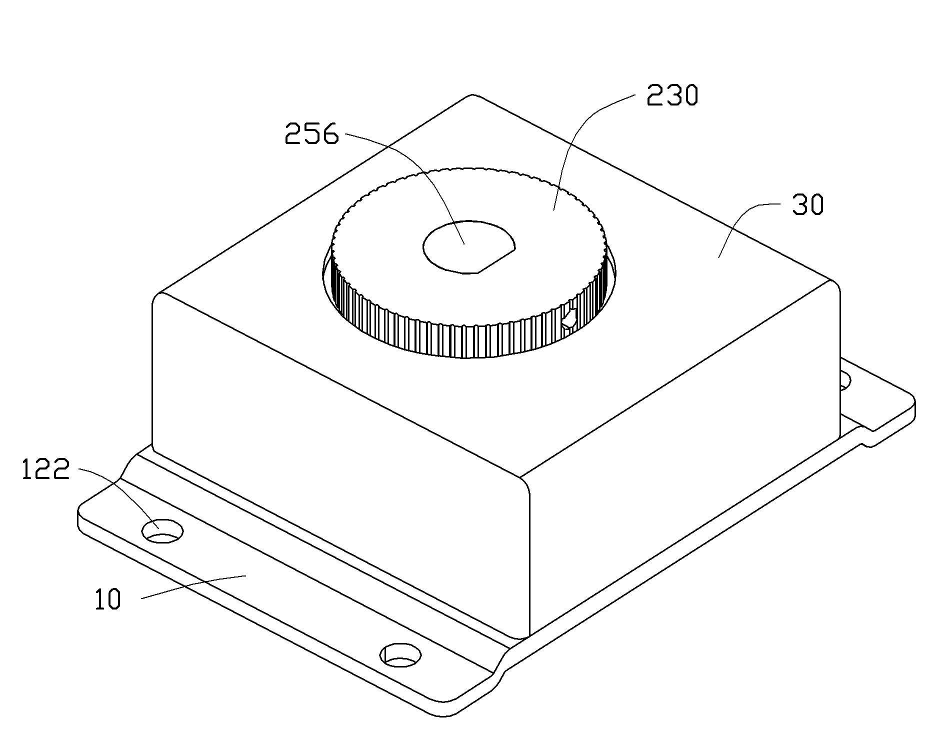
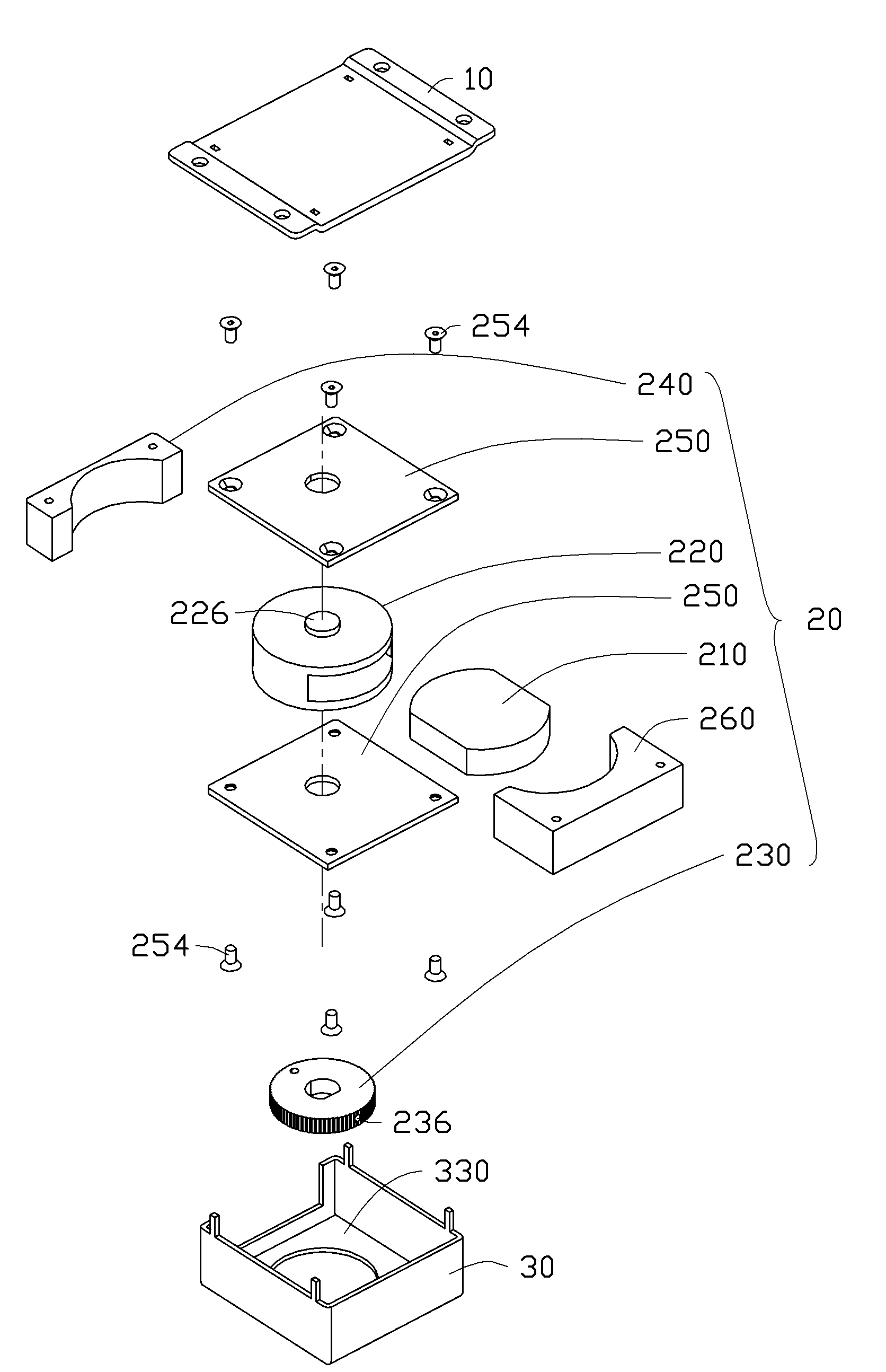
[0051] Please see figure 1 with figure 2 , the magnetic lock device 100 cooperates with an adsorption device (not shown) for locking doors, windows and the like. The adsorption device is a metal that can be attracted by the magnetic material, for example, a piece of iron. The magnetic lock device 100 includes a base plate 10 , a cover body 30 engaged with the base plate 10 , and a lock body 20 accommodated between the base plate 10 and the cover body 30 .

[0052] Please also refer to figure 2 with image 3 , The bottom plate 10 is substantially rectangular. The middle portion of the bottom plate 10 arches upwards to form a rectangular base 110 . Two fixing portions 120 are formed on two opposite edges of the base portion 110 . The two fixing parts 120 are symmetrical to the base part 110 . Two symmetrical engaging holes 112 are respectively defined on two edges of the base portion 110 adjacent to the fixing portion 120 . The two engaging holes 112 on one edge are di...


PUM


Abstract

The invention provides a magnetic lock device, which comprises a lock body. The lock body comprises a magnetic piece for generating a constant magnetic force, a bearing body for bearing the magnetic piece, and a magnetic conductor for conducting the magnetic piece. The magnetic conductor is made by materials which are not easily be magnetized. The bearing body is rotatablely arranged at one side of the magnetic conductor. When the bearing body rotates relative to the magnetic conductor under the action of an external force, the bearing body drives the magnetic piece to rotate relative to the magnetic conductor, so that the number of magnetic force lines passing through the magnetic conductor is changed, and the attractive force of the magnetic lock device is changed. By means of the magnetic lock device, a user can adjust the magnitude of the magnetic force of the magnetic lock device to meet different magnetic force requirements.

Description

technical field [0001] The invention relates to a magnetic lock device, in particular to a magnetic lock device with adjustable magnetic force. Background technique [0002] At present, most of the common magnetic locks on the market are composed of a lock body that can generate magnetic force and an adsorption device that can be absorbed by the lock body. The lock body includes a permanent magnet. However, permanent magnets generate a constant magnetic force. Therefore, a certain type of magnetic lock of this kind of magnetic force lock cannot be applied to a device whose required magnetic force is different from that of the magnetic force of this type of magnetic force lock, and the applicability is relatively poor. In addition, when lock bodies with different magnetic forces are required, different types of magnets need to be selected to design the magnetic lock so that the magnetic lock can generate different magnetic forces, which increases the complexity of the desig...

Claims


Application Information

Patent Timeline
Patent Type & Authority Patents(China)
IPC IPC(8): E05B47/06E05B15/16
Inventor 王禄新
Owner STATE GRID CORP OF CHINA
Features
  • R&D
  • Intellectual Property
  • Life Sciences
  • Materials
  • Tech Scout
  • Unparalleled Data Quality
  • Higher Quality Content
  • 60% Fewer Hallucinations
Learn More