Supercharge Your Innovation With Domain-Expert AI Agents!

Catalyst thin layer and method for fabricating the same

A catalyst and thin layer technology, applied in the field of catalyst thin layer and its manufacture, can solve the problems of difficult access to catalytic sites and the like

Inactive Publication Date: 2011-10-05
COMMISSARIAT A LENERGIE ATOMIQUE ET AUX ENERGIES ALTERNATIVES +1
View PDF4 Cites 4 Cited by
  • Summary
  • Abstract
  • Description
  • Claims
  • Application Information

AI Technical Summary

Problems solved by technology

Also, access to the catalytic site can be difficult

Method used


Image

  • Catalyst thin layer and method for fabricating the same
  • Catalyst thin layer and method for fabricating the same
  • Catalyst thin layer and method for fabricating the same

Examples


Embodiment Construction

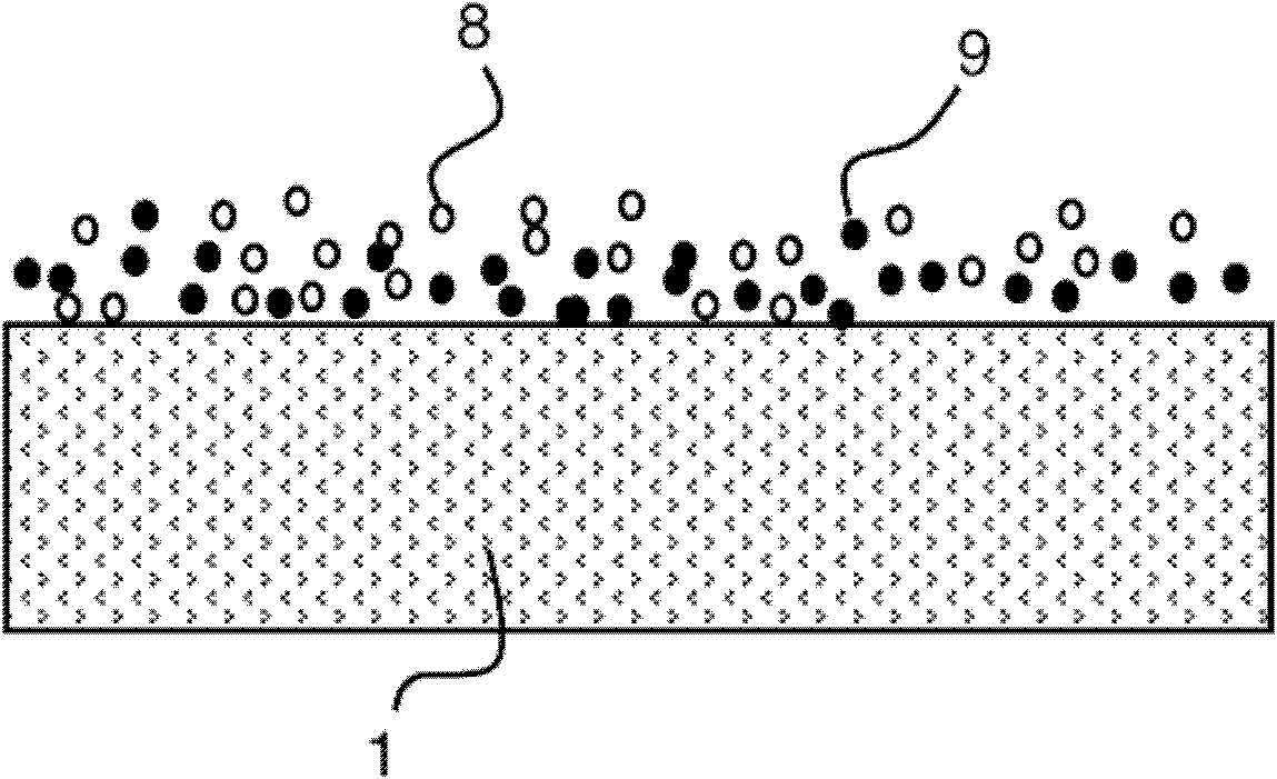
[0021] refer to Figure 4 , the thin catalyst layer 11 consists of electronically conductive catalyst nanoparticles 12 embedded in a polymer matrix 13 . The thin catalyst layer 11 has a preferred thickness of less than or equal to 2 μm. Catalyst nanoparticles 12 are embedded in said polymer matrix 13 without any other support and electron conduction is ensured in the catalyst layer 11 by a percolation mechanism. The exclusion of carbon particles 9 according to the prior art enhances electron conduction, since catalyst nanoparticles 12 are more electrically conductive than carbon particles 9 . However, at low catalyst atomic percentages, ie, when the ratio of catalyst atoms / total number of atoms is low, the electronically conductive catalyst nanoparticles 12 are dispersed in the polymer matrix 13 . They are too far apart from each other to be reached by electrons provided, for example, by electrochemical reactions. On the other hand, at high catalyst atomic percentages, elect...


PUM

PropertyMeasurementUnit
electrical conductivityaaaaaaaaaa
particle diameteraaaaaaaaaa

Abstract

The catalyst thin layer 11 consists of electronically conductive catalyst nano- particles 12 embedded in a polymeric matrix 13. The ratio number of catalyst atoms / total number of atoms in the catalyst layer 11 is comprised between 40 % and 90 %, more preferably between 50% and 60%.

Description

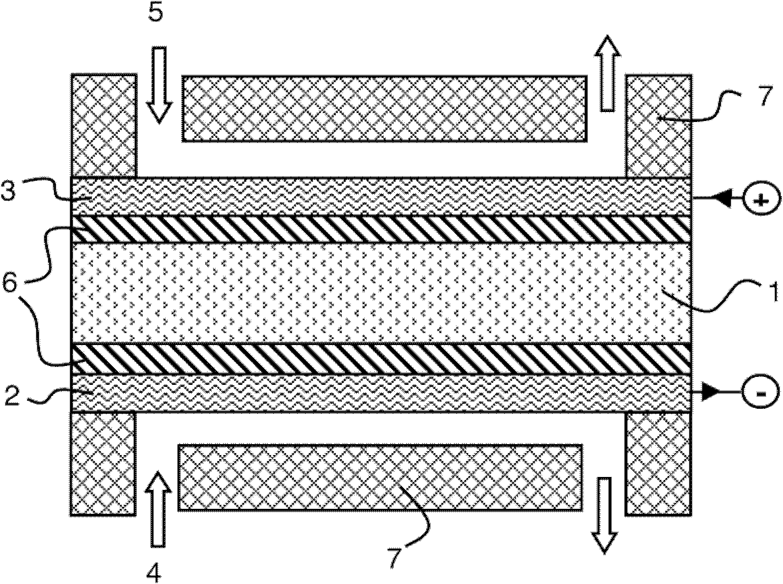
technical field [0001] The present invention relates to a thin catalyst layer and a method for its manufacture. The invention also relates to a fuel cell catalytic electrode comprising said catalyst thin layer. Background technique [0002] Thin layers of catalysts are used in many applications to facilitate reactions. For example, they can be used in energy systems such as catalyst combustion systems or in sensor systems such as glucose, hydrogen or oxygen detectors as well as in miniature systems such as micro-electro-mechanical systems (MEM), lab-on-chip (LabOn-chip) or microfluidic systems . Catalyst thin layers are more particularly used in the manufacture of catalytic electrodes for fuel cells. [0003] The basic structure of a fuel cell is schematically shown in FIG. 1 . The fuel cell comprises an electrolyte material 1 sandwiched between two electrodes such as a porous anode 2 and a porous cathode 3 . An electrochemical reaction takes place between the fuel gas ...

Claims


Application Information

Patent Timeline
Patent Type & Authority Applications(China)
IPC IPC(8): H01M4/86H01M4/88H01M8/10H01M4/92
CPCH01M4/8605Y02E60/50H01M4/881H01M4/8652Y02E60/521H01M4/921
Inventor 史蒂夫·马丁里卡多·达戈斯蒂诺安托万·拉图尔安托内拉·米莱拉法比奥·帕隆博杰西卡·特里
Owner COMMISSARIAT A LENERGIE ATOMIQUE ET AUX ENERGIES ALTERNATIVES
Features
  • R&D
  • Intellectual Property
  • Life Sciences
  • Materials
  • Tech Scout
  • Unparalleled Data Quality
  • Higher Quality Content
  • 60% Fewer Hallucinations
Learn More