Check patentability & draft patents in minutes with Patsnap Eureka AI!

Coiling method for controlling folding defects in flat strip coiling

A strip steel and flattening technology, which is applied in the coiling of strip steel and the coiling field to control the folding defects of flat strip steel coiling, and can solve the problems of product drop group, aggravated folding defects, large coiling tension, etc.

Inactive Publication Date: 2011-12-21
PANZHIHUA IRON AND STEEL +1
View PDF5 Cites 19 Cited by
  • Summary
  • Abstract
  • Description
  • Claims
  • Application Information

AI Technical Summary

Problems solved by technology

[0002] At present, when cold-rolled coils in the domestic metallurgical industry are coiled on the skin-passing unit, the strip head is directly in contact with the fan-shaped block of the reel body of the coiler through the belt coiler. There are crease defects on the surface of the strip caused by the head and the reel sector. The length of the strip with the crease defect on the surface is about 60-120m / coil. The thinner the strip, the crease defect caused by the reel sector The more serious, the thicker the strip steel, the more serious the crease defects on the strip surface caused by the strip head, the light crease defects on the strip surface will lead to product downgrading, and the severe ones will directly cause product scrapping
The main reason for the above-mentioned folding defects is that during the coiling process, since the strip steel is directly in contact with the reel body of the coiler, and the reel body of the coiler is composed of at least three sector blocks, it will On the surface of the strip steel in the inner ring of the steel coil, there is a crease defect similar to the outer arc length of the fan-shaped block; in addition, when coiling, the coiling tension is relatively high, so that the strip steel coil on the outside is squeezed on the inside with a large pressure On the strip steel coil, the formation of fold defects is further aggravated

Method used


Image

  • Coiling method for controlling folding defects in flat strip coiling
  • Coiling method for controlling folding defects in flat strip coiling

Examples


Embodiment Construction

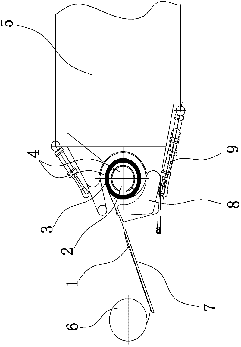
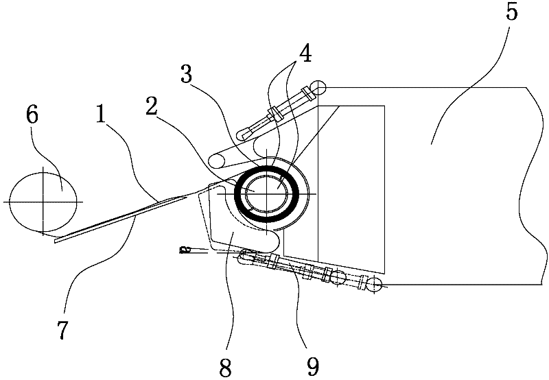
[0014] Such as figure 1 Shown is a coiling method provided by the present invention that can effectively reduce crease defects formed in the coiling process of the flat steel strip and control the crease defects in coiling of the flat steel strip. The coiling method comprises the following steps,

[0015] First, on the outer surface of the reel body 2 of the coiler for coiling strip steel 1, an elastic buffer layer is installed to form a coiler reel 4; On the take-up machine; then start the belt coiler 5, so that the reel 4 of the coiler enters the belt coiler 5, at the same time, start the tension roller group of the leveling unit, and pass the strip steel 1 through the outlet tension roller of the tension roller group 6 and the outlet guide plate 7 are transported to the outer surface of the coiler drum 4, and are coiled to the outer surface of the coiler drum 4 with the assistance of the belt coiler 5; when the strip 1 is on the coiler After the outer surface of the reel ...


PUM


Abstract

The invention discloses a coiling method for controlling the coiling defect of flat strip steel, which belongs to the technical field of metallurgical production. The invention provides a coiling method for controlling the crease defect in the coiling of the tempered strip steel which can effectively reduce the crease defect formed in the process of coiling the steel strip by a tempering machine. The coiling method includes the following steps: first, on the outer surface of the coiler drum body, an elastic buffer layer is installed to form the coiler drum; then the coiler drum is installed on the coiler; then the belt is started Coiler, make the coiler reel into the belt coiler, at the same time, start the tension roller group, convey the strip to the outer surface of the coiler drum, and with the assistance of the belt coiler Coiled to the outer surface of the coiler reel; when the strip is coiled to no less than three layers on the outer surface of the coiler reel, start the belt coiler again to move the coiler reel out The belt assembly aid completes the coiling process of the strip, and then enters the coiling of the intermediate process of the strip.

Description

technical field [0001] The invention relates to a strip steel coiling method, in particular to a coiling method for controlling flat strip steel coiling fold marks, and belongs to the technical field of metallurgical production. Background technique [0002] At present, when cold-rolled coils in the domestic metallurgical industry are coiled on the skin-passing unit, the strip head is directly in contact with the fan-shaped block of the reel body of the coiler through the belt coiler. There are crease defects on the surface of the strip caused by the head and the reel sector. The length of the strip with the crease defect on the surface is about 60-120m / coil. The thinner the strip, the crease defect caused by the reel sector The more serious, the thicker the strip steel is, and the more serious the crease defects on the strip surface caused by the strip head are. The light crease defects on the strip steel surface will lead to product downgrading, and the serious ones will d...

Claims


Application Information

Patent Timeline
IPC IPC(8): B21C47/04B21C47/30
Inventor 向安平何明
Owner PANZHIHUA IRON AND STEEL
Features
  • R&D
  • Intellectual Property
  • Life Sciences
  • Materials
  • Tech Scout
  • Unparalleled Data Quality
  • Higher Quality Content
  • 60% Fewer Hallucinations
Learn More