Supercharge Your Innovation With Domain-Expert AI Agents!

Internal combustion engine

A technology of internal combustion engine and fuel, which is applied in the direction of internal combustion piston engine, combustion engine, mechanical equipment, etc., can solve the problems of fuel injection system cost increase, increase air density, reduce performance impact, prevent exhaust performance and combustion The effect of poor consumption

Active Publication Date: 2015-04-29
MITSUBISHI MOTORS CORP
View PDF5 Cites 0 Cited by
  • Summary
  • Abstract
  • Description
  • Claims
  • Application Information

AI Technical Summary

Problems solved by technology

Therefore, in an internal combustion engine having a direct injection injector, there is a problem that the cost of the fuel injection system increases

Method used


Image

  • Internal combustion engine
  • Internal combustion engine
  • Internal combustion engine

Examples


Embodiment Construction

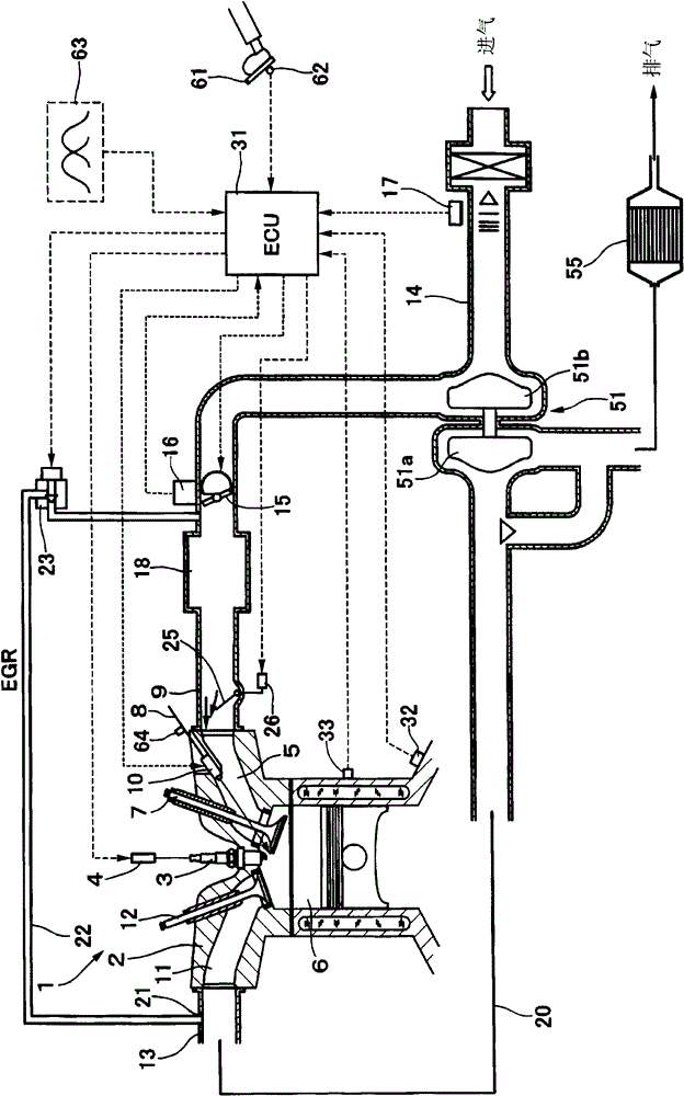
[0038] will refer to figure 1 and figure 2 The internal combustion engine of the present invention will be described.

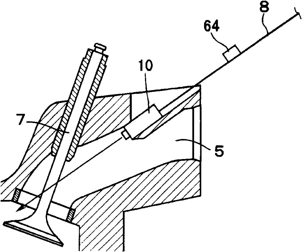
[0039] figure 1 shows a schematic block diagram of an entire internal combustion engine according to an embodiment of the present invention, and figure 2 The structure around the air intake is shown.

[0040] according to figure 1 and figure 2As shown, for each cylinder, a spark plug 3 is engaged to a cylinder head 2 of an engine body 1 (hereinafter, referred to as "engine") as an internal combustion engine, and an ignition coil 4 outputting a high voltage is connected to the spark plug 3 . Further, intake ports 5 (intake passages) are formed in the cylinder head 2 of each cylinder, and intake valves 7 are mounted on the combustion chamber 6 side of each intake port 5, respectively. The intake valves 7 are opened and closed following a cam of a camshaft (not shown) that rotates according to the rotation of the engine, thus allowing communication and / ...


PUM


Abstract

An internal combustion engine includes an injector that injects a fuel into an intake passage. A first injection means injects the fuel from the injector in an intake stoke. A second injection means injects the fuel from the injector in an exhaust stroke. A comparison means compares a pressure in the intake passage and a pressure in an exhaust passage. An injection controller controls an operation ratio of the first injection means and the second injection means, according to a rotation speed of the internal combustion engine, a load, and conditions of the pressures obtained by the comparison means.

Description

technical field [0001] The present invention relates to an internal combustion engine capable of controlling the injection condition of fuel flowing into an intake manifold so that the performance of the internal combustion engine is improved without providing a fuel injection device inside a cylinder for directly injecting fuel into the cylinder. Background technique [0002] As an internal combustion engine, there is known an engine in which a direct injection injector for directly injecting fuel into the cylinder is provided inside a cylinder and a port injector for injecting fuel into the intake passage is provided in the intake passage ( See JP-A-2009-228447). [0003] In an engine having a direct injection injector and a port injector, by directly injecting high-pressure fuel from the direct injection injector into the cylinder, it is possible to concentrate the air-fuel mixture in which the fuel is denser around the spark plug. Therefore, due to so-called stratified ...

Claims


Application Information

Patent Timeline
Patent Type & Authority Patents(China)
IPC IPC(8): F02D41/30F02D13/02
CPCF02B25/145F02B31/06F02B2275/48F02D13/0207F02D13/0261F02D41/0007F02D41/1448F02D41/345F02D41/402F02D2041/001F02D2200/0406F02D2200/0602F02M26/05F02M26/10Y02T10/12Y02T10/40F02D41/34F02D41/40F02M45/02F02M45/08
Inventor 田中大
Owner MITSUBISHI MOTORS CORP
Features
  • R&D
  • Intellectual Property
  • Life Sciences
  • Materials
  • Tech Scout
  • Unparalleled Data Quality
  • Higher Quality Content
  • 60% Fewer Hallucinations
Learn More