A water throwing device driven by friction wheel
A friction wheel transmission and friction wheel technology, which is applied in the field of water throwing devices for air conditioners, can solve problems such as affecting the cooling effect, and achieve the effect of improving energy efficiency and good transmission effect.
- Summary
- Abstract
- Description
- Claims
- Application Information
AI Technical Summary
Problems solved by technology
Method used
Image

Examples
Example Embodiment
[0025] Example 1:
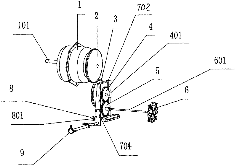
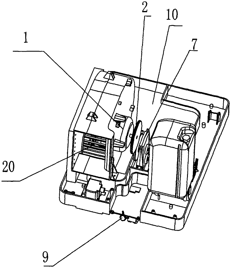
[0026] Such as Figure 1 to Figure 3-2 As shown, a water throwing device using friction wheel transmission includes a motor 1, a motor shaft 101, a large friction wheel 2, a small friction wheel 3, a large gear 4, a large gear drive shaft 401, a small gear 5, and a water throwing impeller 6. , Impeller drive shaft 601, water slinger 7, water slinger rail 8 and water slinger control switch 9; the large friction wheel 3 is fixedly installed at the outer end of the motor shaft 101; the middle of the large gear drive shaft 401 passes through the upper hole of the water slinger 7, In rolling connection with the water sling 7, the small friction wheel 3 is fixedly installed at the inner end of the large gear drive shaft 401; the large friction wheel 2 and the small friction wheel 3 are in the same vertical plane, the large friction wheel 2 is on the top, and the small friction wheel 3 is on the bottom. , The edges of the two friction wheels are tangent, and they are...
Example Embodiment
[0033] Example 2:
[0034] Such as Figure 3-1 to Figure 6 As shown, the motor is a synchronous wheel motor 14 and the motor shaft is a synchronous wheel motor shaft 141. It also includes a small synchronous wheel 15, a synchronous belt 16, a large synchronous wheel 17 and a friction wheel shaft 18. The large synchronous wheel 17 is fixedly mounted on On the friction wheel shaft 18, the large synchronous wheel 17 is in transmission connection with the small synchronous wheel 15 through the synchronous belt 16, and the small synchronous wheel 15 is fixedly connected with the synchronous wheel motor shaft 141; at this time, the large friction wheel 2 is fixedly installed at the outer end of the friction wheel shaft 18. The same as in Example 1.
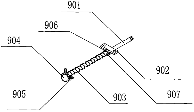
[0035] The present invention adopts the water throwing process when the synchronous wheel motor is used: when the machine is cooling, the water throwing control switch 9 can be adjusted, the water throwing control switch handle 905 is rotat...
PUM
 Abstract
Description
Claims
Application Information
 - R&D Engineer
- R&D Manager
- IP Professional
- Industry Leading Data Capabilities
- Powerful AI technology
- Patent DNA Extraction
Browse by: Latest US Patents, China's latest patents, Technical Efficacy Thesaurus, Application Domain, Technology Topic.
© 2024 PatSnap. All rights reserved.Legal|Privacy policy|Modern Slavery Act Transparency Statement|Sitemap