Supercharge Your Innovation With Domain-Expert AI Agents!

Eccentrically swing type reduction gear

A technology of eccentric swing and reducer, which is applied in the direction of mechanical equipment, transmission devices, gear transmission devices, etc., and can solve the problems of inability to fully replace new grease, difficulty in passing grease, and difficulty in spreading grease, etc.

Active Publication Date: 2014-06-25
SUMITOMO HEAVY IND LTD
View PDF7 Cites 0 Cited by
  • Summary
  • Abstract
  • Description
  • Claims
  • Application Information

AI Technical Summary

Problems solved by technology

[0008] However, since these gaps are so narrow, it is difficult for grease to pass through this gap
As a result, for example, when new grease is resealed inside the reducer 1, there is a problem that the grease does not easily spread to every corner of the reducer 1.
In addition, when replacing the old grease sealed inside the reducer 1 with new grease, it is difficult to discharge all the old grease from the inside of the reducer 1, and as a result, there is a possibility that the new grease cannot be replaced sufficiently.

Method used


Image

  • Eccentrically swing type reduction gear
  • Eccentrically swing type reduction gear
  • Eccentrically swing type reduction gear

Examples


Embodiment Construction

[0025] Hereinafter, an eccentric oscillating type speed reducer 100 according to an example of an embodiment of the present invention will be described in detail with reference to the drawings.

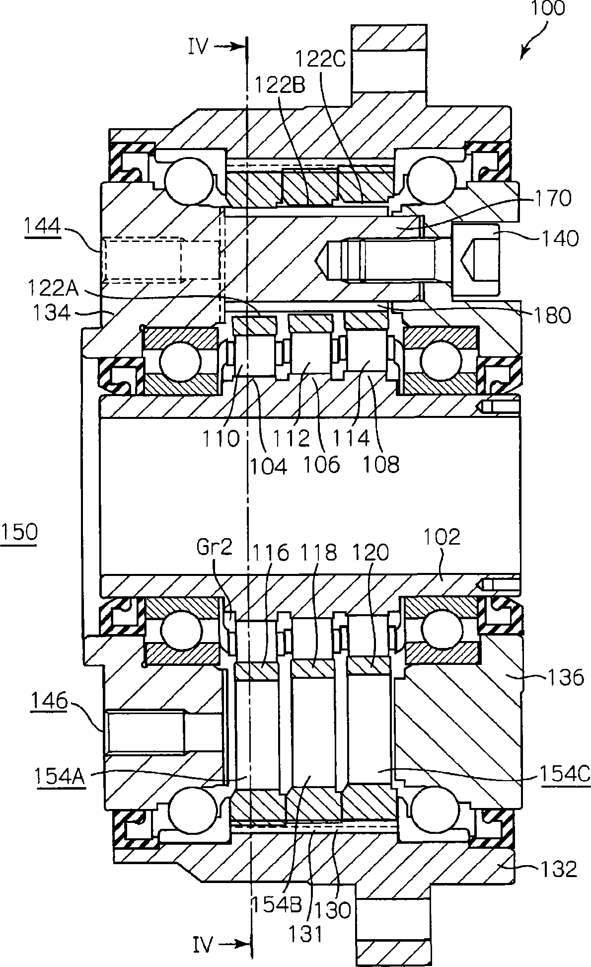
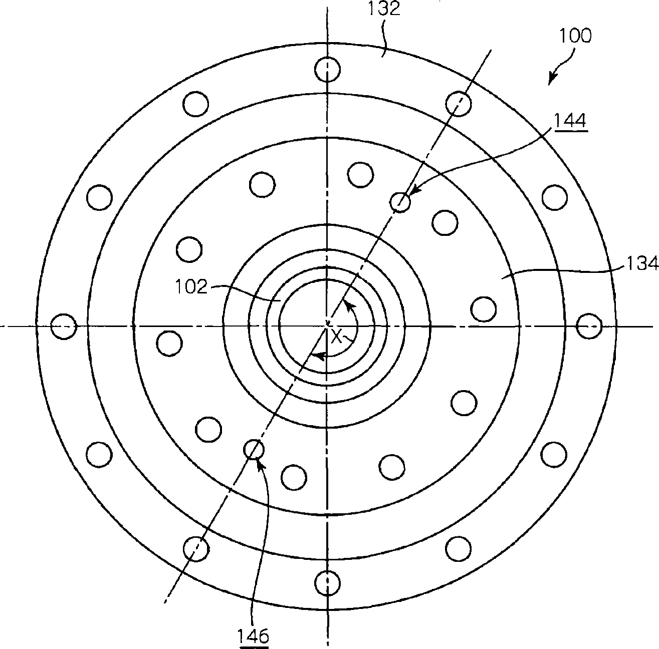
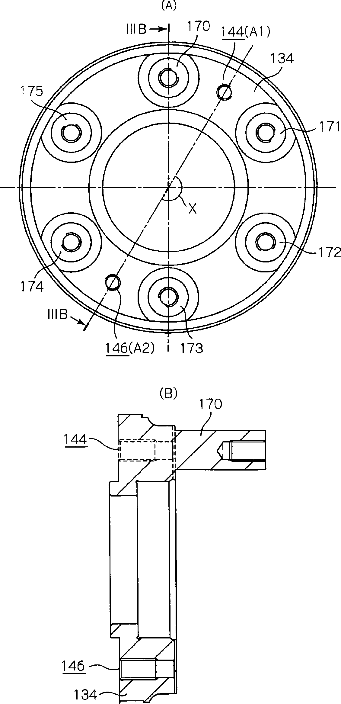
[0026] figure 1 It is a longitudinal sectional view of the eccentric oscillating speed reducer 100 . and, figure 2 yes means figure 1 The front view of the positions of the grease supply and discharge ports 144 and 146 in the reduction gear 100 is shown. image 3 Viewed from the side of the first external gear 116 figure 1 The rear view of the first flange body 134 provided in the shown reducer 100 ( image 3 (A)) and along image 3 The cross-sectional view of the arrow IIIB-IIIB line of the first flange body 134 shown in (A) ( image 3 (B)). Figure 4 is along figure 1 It is a sectional view of the arrow IV-IV line of the reduction gear 100 shown.

[0027] First, the overall structure of the eccentric oscillating speed reducer 100 will be described.

[0028] The eccent...


PUM


Abstract

The invention provides an eccentrically swing type reduction gear, which enables grease to be easily spread in the reduction gear. The eccentrically swing type reduction gear (100) comprises external gears (116, 118, 120) which swing eccentrically, an internal gear (130) which is internally engaged with the external gears (116, 118, 120) and has internal teeth which are slightly different from external teeth of the external gears (116, 118, 120) in terms of the tooth amount, and flanges (134) which are disposed at axial side portions of the external gears (116, 118, 120). The flanges (134) have at least one of a grease supply port (144) and a grease discharge port (146). In addition, the external gears (116, 118, 120) are axially penetrated, so that through holes (152A, 154A, 154B, 154C) are formed without penetrating through components of the speed reducer (100).

Description

technical field [0001] This application claims priority based on Japanese Patent Application No. 2010-142060 filed on June 22, 2010. The entire content of this application is used by reference in this specification. [0002] The invention relates to an eccentric oscillating reducer. Background technique [0003] In Patent Document 1, it is disclosed as Figure 10 The eccentric oscillating type reducer 1 shown. [0004] The eccentric oscillating speed reducer 1 includes an eccentrically oscillating external gear 2 and an internal gear 3 internally meshing with the external gear 2 . The internal teeth 3A of the internal gear 3 and the external teeth 2A of the external gear 2 have a very small difference in the number of teeth. Further, a flange 4 is arranged on an axial side portion of the external gear 2 , and a grease supply port 5 for supplying grease into the reduction gear 1 is formed on the flange 4 . [0005] Patent Document 1: Japanese Unexamined Patent Publication...

Claims


Application Information

Patent Timeline
Patent Type & Authority Patents(China)
IPC IPC(8): F16H1/32F16H57/04F16H55/17
Inventor 芳贺卓志津庆刚
Owner SUMITOMO HEAVY IND LTD
Features
  • R&D
  • Intellectual Property
  • Life Sciences
  • Materials
  • Tech Scout
  • Unparalleled Data Quality
  • Higher Quality Content
  • 60% Fewer Hallucinations
Learn More