Check patentability & draft patents in minutes with Patsnap Eureka AI!

Method for manufacturing a long micro lens array

A technology of microlens array and microlens, which is applied in the direction of microlithography exposure equipment, exposure device of photolithography process, photoplate process of pattern surface, etc.

Inactive Publication Date: 2014-05-21
CARL ZEISS SMT GMBH
View PDF11 Cites 0 Cited by
  • Summary
  • Abstract
  • Description
  • Claims
  • Application Information

AI Technical Summary

Problems solved by technology

However, this method involves multiple exposure and etching steps that can only reproduce with limited accuracy
As a result, the surface profiles of microlens arrays generated by this method have tolerances that are often out of specification

Method used


Image

  • Method for manufacturing a long micro lens array
  • Method for manufacturing a long micro lens array
  • Method for manufacturing a long micro lens array

Examples


Embodiment Construction

[0080] 1. Optical Integrator

[0081] The general structure and function of the optical integrator according to the present invention will be described below.

[0082] 1.1 General structure

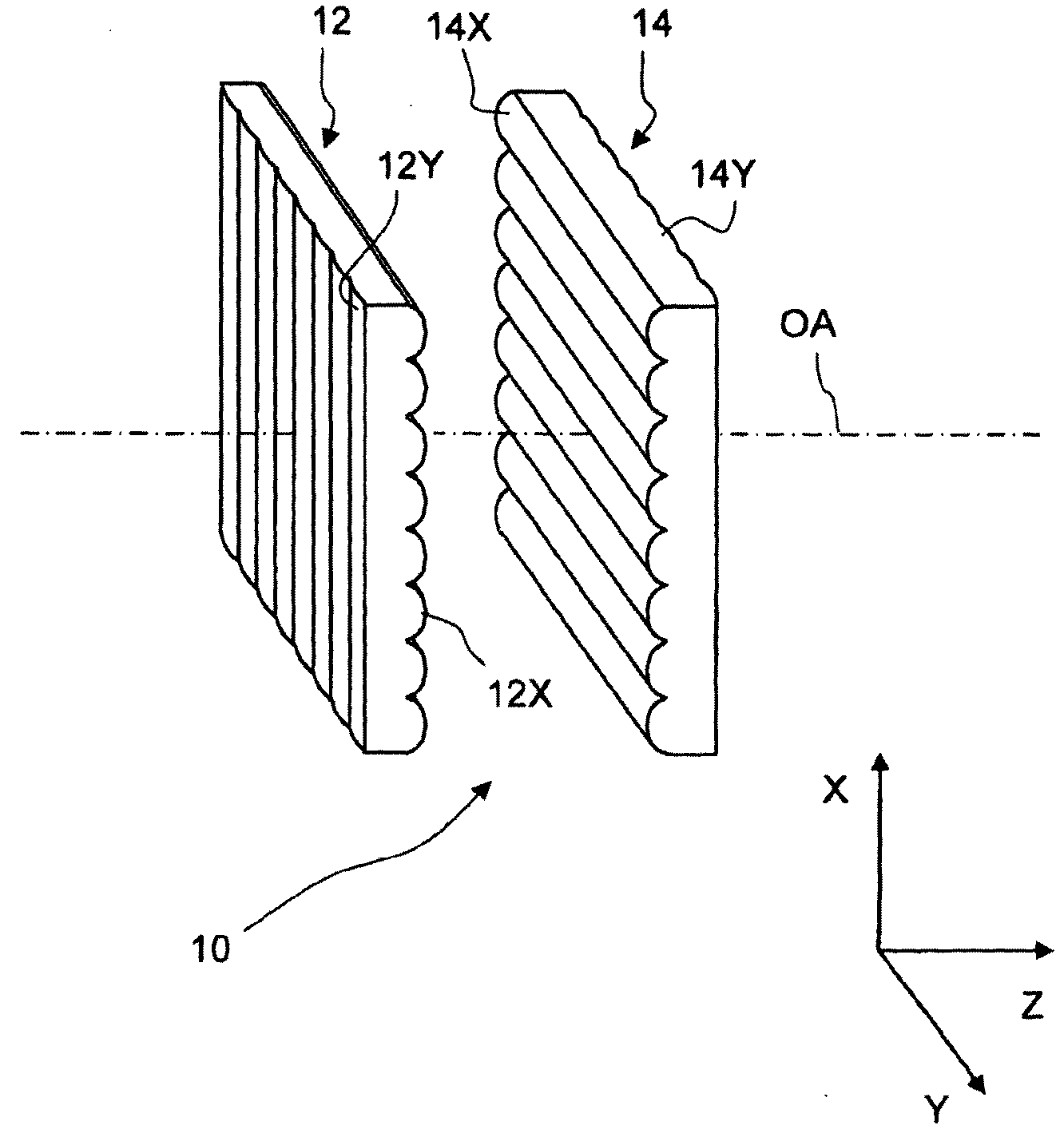
[0083] figure 1 is a perspective view of a simplified optical integrator, denoted by 10 as a whole. The optical integrator 10 of this embodiment is composed of a first integrator part 12 and a second integrator part 14 . The first integrator component 12 comprises a first array of cylindrical microlenses 12Y having parallel longitudinal axes aligned along the X direction. The first integrator component 12 also includes a second array of cylindrical microlenses 12X having parallel longitudinal axes aligned along a Y direction perpendicular to the X direction. Because the longitudinal axes of the microlenses 12X, 12Y are straight lines, the first microlens 12Y has refractive power only along the Y direction, while the second microlens 12X has refractive power only in the X direction.

...


PUM


Abstract

The disclosure relates to an optical integrator configured to produce a plurality of secondary light sources in an illumination system of a microlithographic projection exposure apparatus. The disclosure also relates to a method of manufacturing an array of elongated microlenses for use in such an illumination system. Arrays of elongated microlenses are often contained in optical integrators or scattering plates of such illumination systems.

Description

[0001] The application date is February 16, 2007, the application number is 200780005771.8 (the international application number is PCT / EP2007 / 001370), and the invention name is "Optical integrator for the irradiation system of microlithography projection exposure equipment" A divisional application of an invention patent application. [0002] Cross References to Related Applications [0003] This application claims priority to US Provisional Applications US Ser. No. 60 / 774,850, filed February 17, 2006, and US Ser. The entire contents of these earlier applications are hereby incorporated by reference. technical field [0004] The invention relates to a method of manufacturing a long microlens array for use in an illumination system of a projection exposure apparatus for microlithography. Long microlens arrays are often included in the optical integrator or diffuser plate of such illumination systems. Background technique [0005] Microlithography (also known as photolitho...

Claims


Application Information

Patent Timeline
Patent Type & Authority Patents(China)
IPC IPC(8): G03F7/20
CPCG03F7/70958G03F7/70075Y10T83/04Y10T83/0304G03F7/70091G03F7/70208H01L21/0274
Inventor O.伍尔夫H.西克曼E.卡尔切布莱纳S.雷南J.旺格勒A.布雷桑M.格哈德N.哈弗坎普A.舍尔茨R.沙恩韦伯尔M.莱S.布尔卡特
Owner CARL ZEISS SMT GMBH
Features
  • R&D
  • Intellectual Property
  • Life Sciences
  • Materials
  • Tech Scout
  • Unparalleled Data Quality
  • Higher Quality Content
  • 60% Fewer Hallucinations
Learn More