Groove milling method for producing IC (Integrated Circuit) intelligent card

A smart card and groove milling technology, applied in the information field, can solve problems such as low production efficiency, slow production speed, and high product rejection rate, and achieve the effect of improving machine efficiency

Inactive Publication Date: 2012-01-25
张开兰
View PDF6 Cites 7 Cited by
  • Summary
  • Abstract
  • Description
  • Claims
  • Application Information

AI Technical Summary

Problems solved by technology

[0011] However, in the production process of the above-mentioned first dual-interface smart card, the precision of the milling process is high, and the precision of most milling machines cannot meet the requirements, and the product rejection rate is high. The specific performance is as follows:
[0012] First, the precision of the milling groove is high. If the depth of the milling groove is not enough, the thread end cannot be picked out; if the depth of the milling groove is too deep, the metal antenna will be damaged or even be milled off, resulting in a waste card;
[0013] Second, in the case of ensuring the accuracy of milling slots, the production speed must be sacrificed, resulting in low production efficiency;
[0014] Third, because the precision requirements for milling grooves are very high, but the precision of most current machines often cannot meet the requirements, so the scrap rate of this process is high
However, in the final stage of slot milling, the feed speed of this machine is extremely slow to prevent damage to the metal antenna, because if the feed speed

Method used


Image

  • Groove milling method for producing IC (Integrated Circuit) intelligent card
  • Groove milling method for producing IC (Integrated Circuit) intelligent card
  • Groove milling method for producing IC (Integrated Circuit) intelligent card

Examples


Example Embodiment

[0044] The present invention will be further described in detail below in conjunction with the drawings.

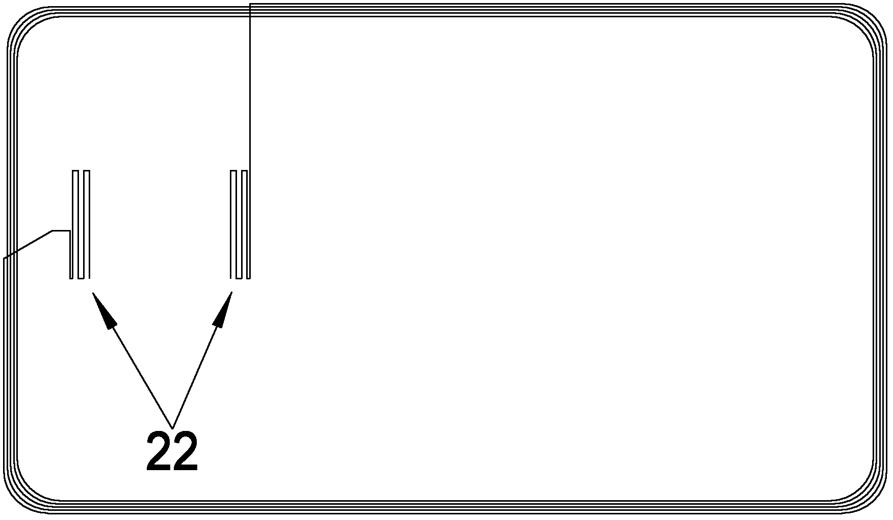
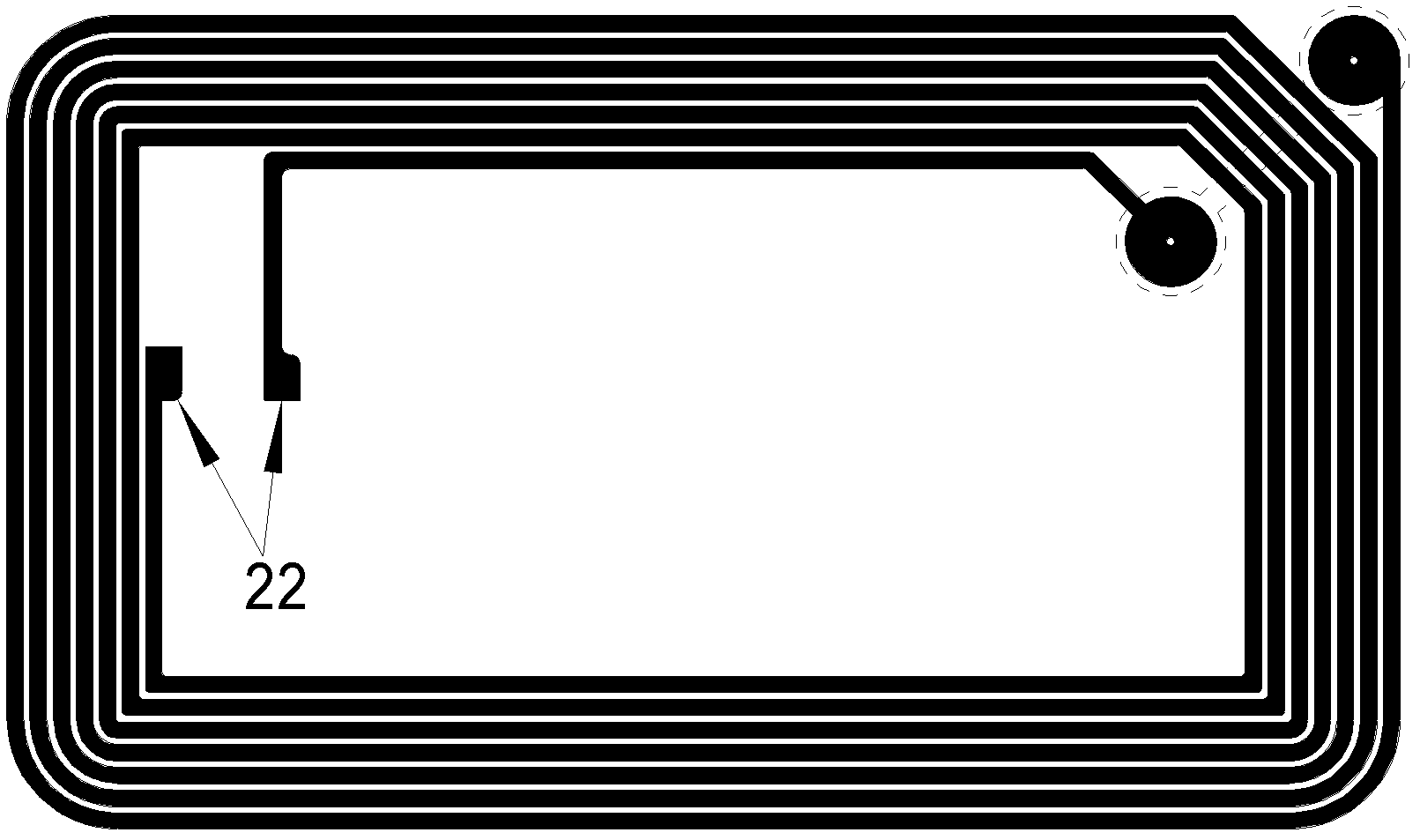
[0045] Because the traditional slot milling process has a poor effect on the production of dual-interface smart cards, especially for the production method of dual-interface smart cards that use ultra-thin antennas instead of ultrasonic-wound antennas, the process of milling slots cannot even be completed. Because the thickness of the metal antenna is not greater than 0.03mm, and the thickness of the electroplated copper antenna is even 0.01mm, no matter whether it is a domestic or imported machine, it is impossible to complete the milling work.

[0046] For this kind of dual-interface smart card, the manufacturing method includes: first, use etching, electroplating or printed antenna as the antenna layer; next, stack the other components of the card base in order, and laminate them, The large semi-finished product is put into the card punching machine and punched into a stand...


PUM


Abstract

The invention discloses a groove milling method for producing an IC (Integrated circuit) intelligent card, which is used for the field of information technology. The groove milling method comprises the following steps of: filling filler pieces in a through hole of a punching layer, and fixing the filler pieces by using a fixing material, wherein the punching layer covers one side of a metal antenna, and the through hole covers two antenna pad areas of an antenna layer; carrying out groove milling on the front surface of a card base of a double-interface card, i.e. the position of the antenna pads, till the filler pieces are exposed, and milling about half thickness of filler pieces off; and sucking the rest filler pieces by vacuum exhausting till the antenna pads are exposed. Therefore, according to the method disclosed by the invention, the problem of the finished product ratio of the double-interface intelligent cards is not high because the groove milling precision is insufficient in the traditional groove milling machine is solved; meanwhile, the high-precision groove milling machine is avoided to be used, and therefore the production cost of the double-interface intelligent card is reduced.

Description

technical field [0001] The invention relates to the field of information technology, in particular to a groove milling method for producing IC smart cards. Background technique [0002] At present, the production process of producing IC smart cards, especially dual-interface smart cards generally includes the following: [0003] Such as figure 1 As shown, the first is the production of the antenna layer. Generally, ultrasonic waves are used to embed copper enameled wires (copper wires coated with high-temperature-resistant insulating varnish) on the antenna substrate to form the antenna layer. The enameled wire diameter is 0.1mm. Since the two ends of the antenna must have proper relative positions to accommodate the two pads of the dual-interface module, one end of the antenna will cross the inner ring from the outer ring to a proper position away from the other end of the antenna. [0004] Next, the other components of the card base are stacked in order and laminated. ...

Claims


Application Information

Patent Timeline
IPC IPC(8): B23C3/28
Inventor 张开兰
Owner 张开兰
Why Eureka
Try Eureka