Coaxial connector for inspection

A technology for coaxial connectors and housings, which is applied in the field of coaxial connectors for inspection, and can solve problems such as the durability of coaxial connectors 101, and achieve excellent durability

Inactive Publication Date: 2012-02-01
MURATA MFG CO LTD
View PDF4 Cites 7 Cited by
  • Summary
  • Abstract
  • Description
  • Claims
  • Application Information

AI Technical Summary

Problems solved by technology

As mentioned above, the coaxial conn

Method used


Image

  • Coaxial connector for inspection
  • Coaxial connector for inspection
  • Coaxial connector for inspection

Examples


Example

[0074] (Other embodiments)

[0075] In addition, the inspection coaxial connector is not limited to the inspection coaxial connector 1 according to the above-mentioned embodiment, and various changes can be made within the scope of the gist.
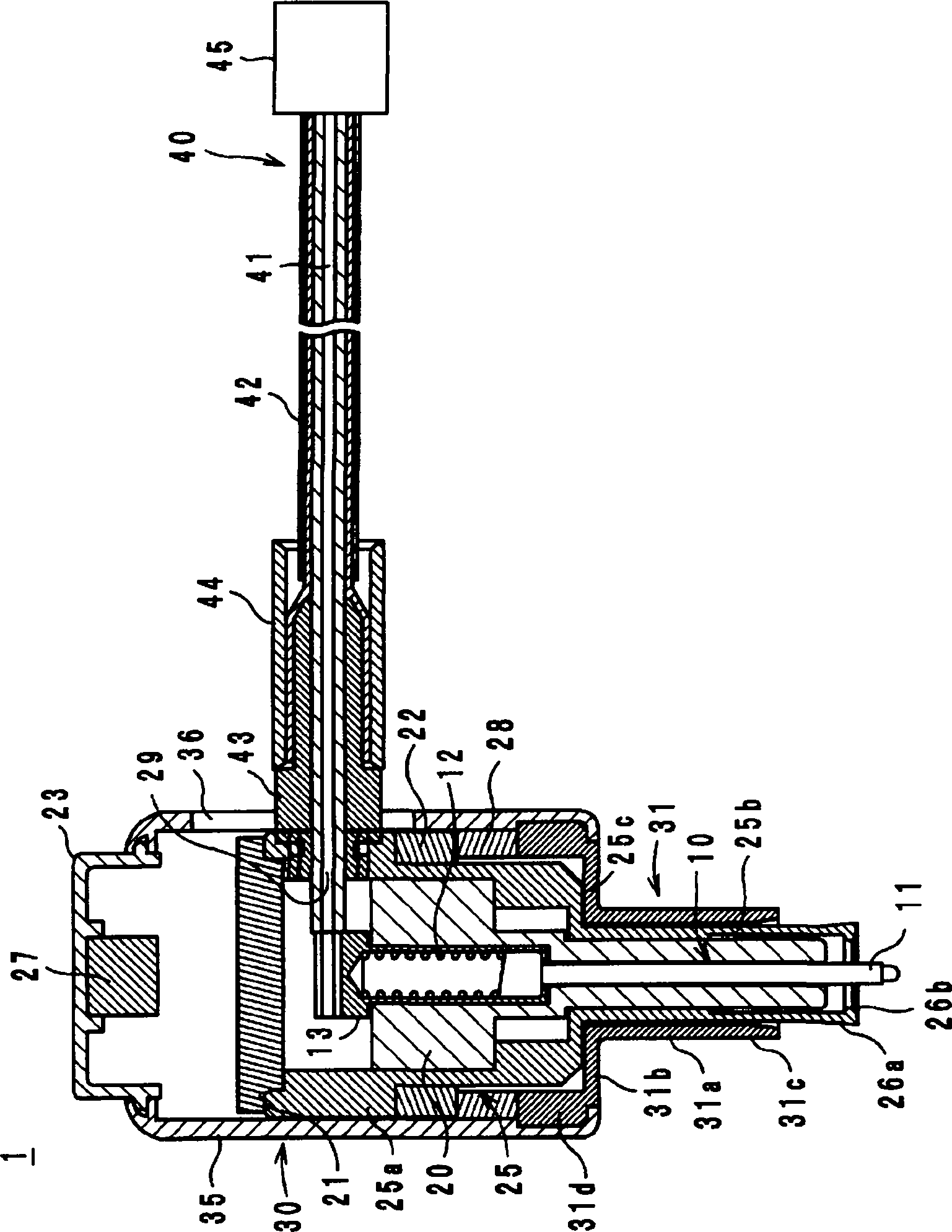
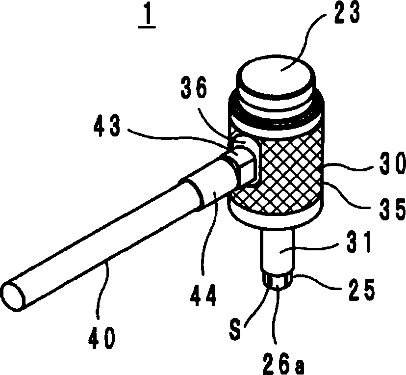
[0076] In the inspection coaxial connector 1, although the yoke 23 and the magnet 27 are mounted on the sleeve 30, and the disk 21 is mounted on the housing 25, the mounting positions of the yoke 23, the magnet 27 and the disk 21 are not limited to this. For example, the yoke 23 and the magnet 27 may be attached to the housing 25, and the disc 21 may be attached to the sleeve 30. However, since it is easier to press the flat disc 21 into the housing 25 than to press the cylindrical yoke 23 into the housing 25, it is preferable to install the yoke 23 and the magnet 27 on the sleeve 30, 25 Install the disc 21.

[0077] In addition, in the inspection coaxial connector 1, the magnet 28 is attached to the sleeve 30 and the suction ring 22 is atta...


PUM


Abstract

Provided is a highly durable coaxial connector for inspection. A housing (25) has a leading edge section (26a) wherein an external conductor is to be inserted, and also has a structure which can increase/reduce the diameter of the leading edge section (26a). A probe (10) extends in the leading edge section (26a). A sleeve (30) has a cylindrical section (31a) having the housing (25) inserted therein. A magnet (28) applies a force to the housing (25) and the sleeve (30) so as to maintain the state wherein the leading edge section (26a) is protruding to the outside of the cylindrical section (31a) when a receptacle is not mounted. The magnet (27) applies a force to the housing (25) and the sleeve (30) so as to maintain the state wherein at least a part of the leading edge section (26a) is housed in the cylindrical section (31a) and that the increase of the diameter of the leading edge section (26a) due to having the leading edge section (26a) in contact with the inner circumferential surface of the cylindrical section (31a) is regulated when the receptacle is mounted.

Description

technical field [0001] The present invention relates to a coaxial connector for inspection, and more specifically, to a coaxial connector for inspection that can be freely attached to and detached from a socket that is an object to be inspected. Background technique [0002] As a conventional coaxial connector for inspection, a coaxial connector described in Patent Document 1 is known. Hereinafter, this coaxial connector will be described with reference to the drawings. Figure 9 It is a cross-sectional structure diagram of the coaxial connector 101 described in patent document 1. Figure 10 is a cross-sectional view of the front end portion of the coaxial connector 101 . exist Figure 9 as well as Figure 10 In , the direction in which the probe 110 protrudes is defined as the up-down direction. [0003] The coaxial connector 101 is arranged at the front end of the coaxial cable not shown, such as Figure 9 As shown, a probe 110 , a coil spring 122 , a housing 125 and a ...

Claims


Application Information

Patent Timeline
IPC IPC(8): H01R24/40H01R24/38
CPCH04M1/24H01R24/40H01R2201/20H01R2103/00H01R13/639
Inventor 剱崎真一若松弘己
Owner MURATA MFG CO LTD
Why Eureka
Try Eureka