Check patentability & draft patents in minutes with Patsnap Eureka AI!

Hydraulic cylinder

A technology of hydraulic cylinder and cylinder liner, applied in the field of hydraulic cylinder, can solve the problems of easy leakage of coolant, poor sealing and stability, affecting the normal operation of hydraulic cylinder, etc., and achieve the effect of easy maintenance and good sealing

Inactive Publication Date: 2012-03-21
陈晓花
View PDF0 Cites 1 Cited by
  • Summary
  • Abstract
  • Description
  • Claims
  • Application Information

AI Technical Summary

Problems solved by technology

The current tightness and stability between the cylinder block and the cylinder liner are not very good, and the coolant is easy to seep out, which affects the normal operation of the hydraulic cylinder

Method used


Image

  • Hydraulic cylinder
  • Hydraulic cylinder

Examples


Embodiment Construction

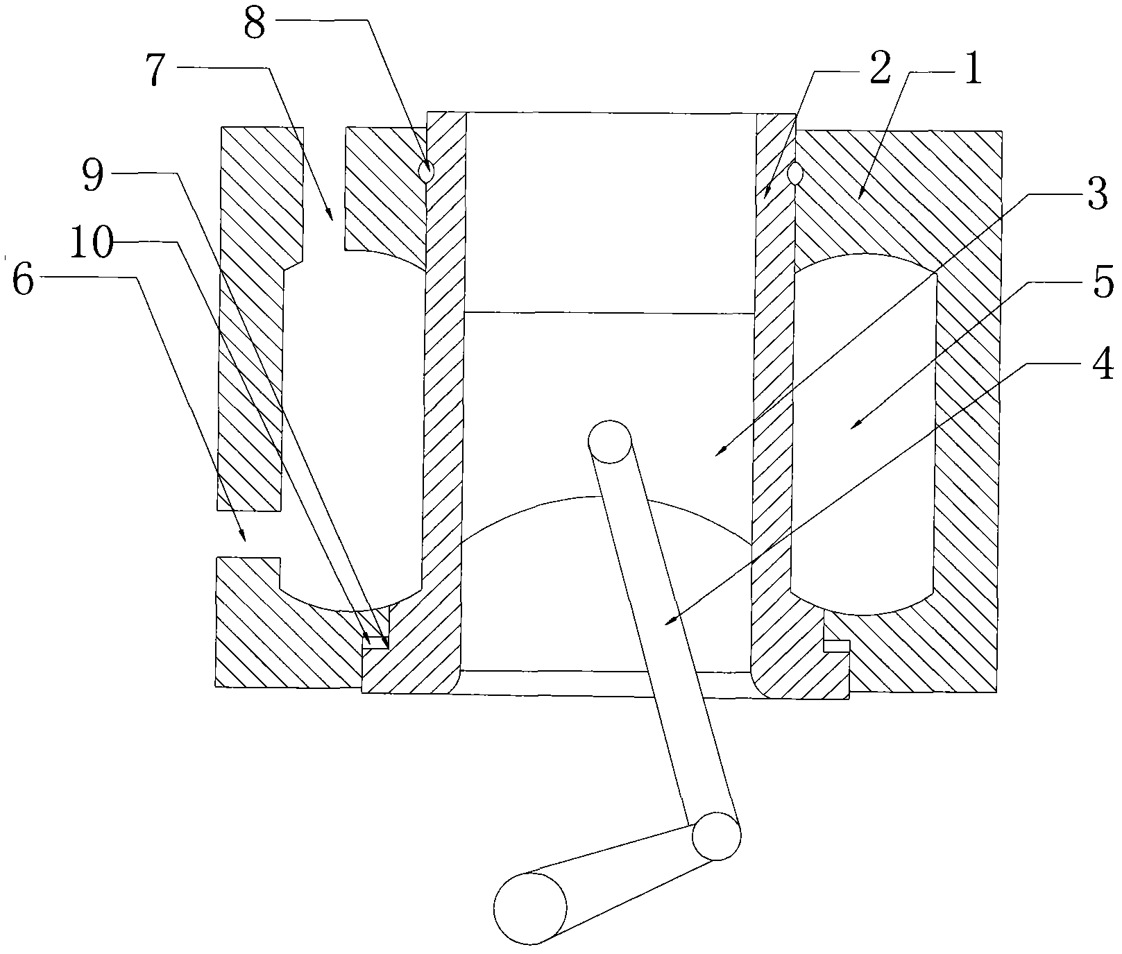
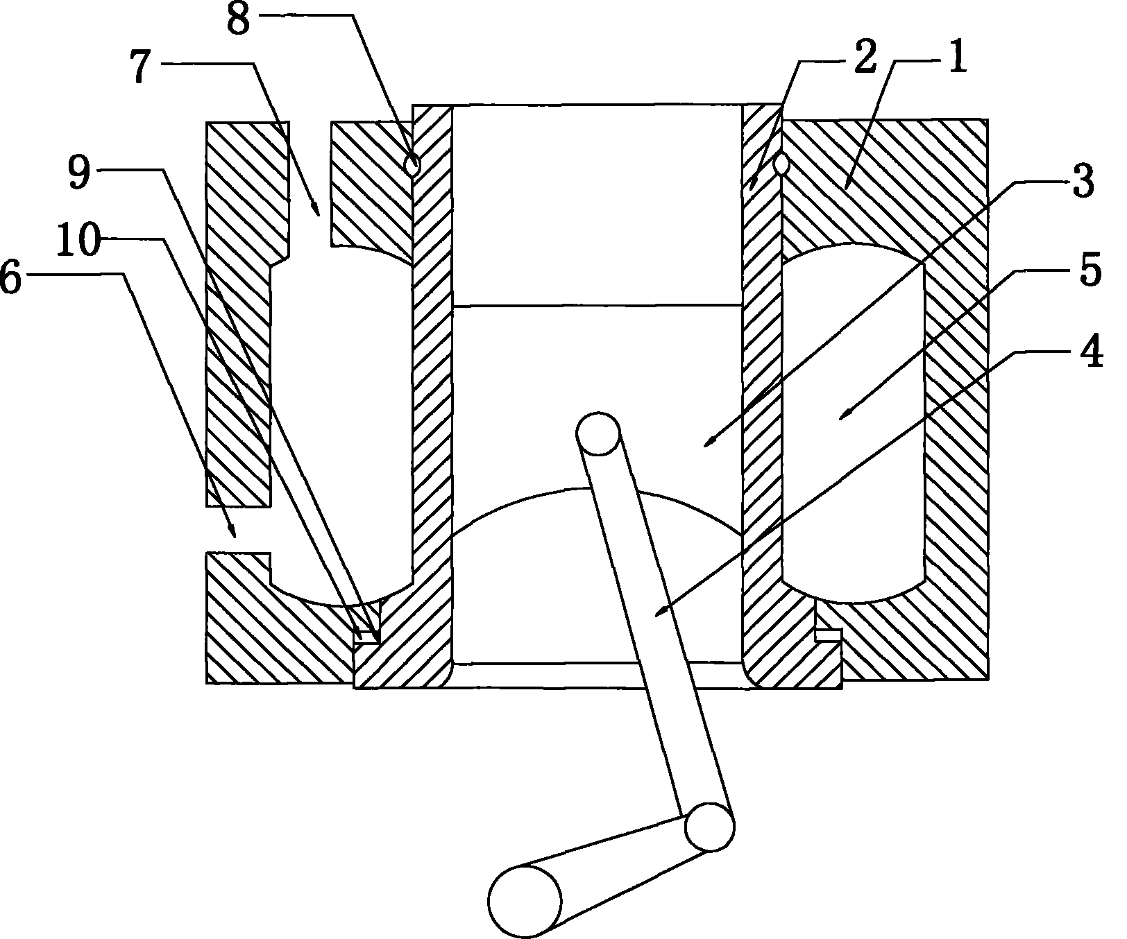
[0012] Such as figure 1 As shown, a hydraulic cylinder includes a cylinder body 1, a cylinder liner 2, a piston 3 placed in the cylinder liner 2 and a piston rod 4 connected to the piston 3, the cylinder body 1 is set on the outer wall of the cylinder liner 2, and the A cooling chamber 5 is left between the body 1 and the cylinder liner 2, and a liquid inlet 6 and a liquid outlet 7 communicating with the cooling chamber 5 are provided on the cylinder body 1. On the outer wall of the cylinder liner 2 above the cooling chamber 5, there is a The groove 8 is provided with a step 9 on the outer wall of the cylinder liner 2 below the cooling chamber 5. In order to enhance the sealing between the cylinder body 1 and the cylinder liner 2, an elastic sealing ring 10 is provided on the groove 8 and the step 9.


PUM


Abstract

The invention relates to a hydraulic cylinder comprising a cylinder body, a cylinder cover, a piston arranged in the cylinder cover, and a piston rod connected with the piston. The cylinder body is sheathed on the outer wall of the cylinder cover, a cooling cavity is reserved between the cylinder body and the cylinder cover, and the cylinder body is provided with a liquid inlet and a liquid outlet which are communicated with the cooling cavity. The hydraulic cylinder is characterized in that a groove is arranged on the outer wall of the cylinder cover above the cooling cavity, and a step is arranged on the outer wall of the cylinder cover below the cooling cavity. The hydraulic cylinder has a good sealing property and strong stability, and is easy to disassemble and convenient to maintain.

Description

technical field [0001] The invention relates to a hydraulic cylinder. Background technique [0002] When the hydraulic cylinder is working, due to the continuous high-speed back and forth movement of the piston, the temperature of the cylinder liner continues to rise. The strength and rigidity of the cylinder liner at high temperature drop sharply, and it is easy to be damaged. For this reason, the cylinder liner needs to be continuously cooled. The existing cooling method is exactly to set up a cylinder body on the outer wall of the cylinder liner, and add cooling liquid in the cylinder body. The sealing and stability between the current cylinder body and the cylinder liner are not very good, and the coolant is easy to seep out, which affects the normal operation of the hydraulic cylinder. Therefore, a new technical solution is needed to solve the above technical problems. Contents of the invention [0003] The purpose of the present invention is to provide a hydrauli...

Claims


Application Information

Patent Timeline
Patent Type & Authority Applications(China)
IPC IPC(8): F15B15/14F15B15/20
Inventor 陈晓花
Owner 陈晓花
Features
  • R&D
  • Intellectual Property
  • Life Sciences
  • Materials
  • Tech Scout
  • Unparalleled Data Quality
  • Higher Quality Content
  • 60% Fewer Hallucinations
Learn More