
Traction pull rod device of railway wagon bogie

A technology for traction rods and railway freight cars, which is applied to bogies, railway car body parts, transportation and packaging, etc., can solve the problems of inconvenient installation of traction rods and heavy structure, avoid fretting wear phenomenon, and meet the requirements of lateral displacement. , The effect of eliminating fretting wear

Active Publication Date: 2012-06-13
CRRC SHANDONG CO LTD
View PDF5 Cites 16 Cited by
  • Summary
  • Abstract
  • Description
  • Claims
  • Application Information

AI Technical Summary

Problems solved by technology

However, since the longitudinal force allowed to be transmitted by railway freight cars is much larger than that of passenger cars or motor cars, if the high-speed freight car bogies without bolster structure want to adopt the traction rod structure mode of bolt force, the bolt diameter of the traction rod must be designed It is very large, which not only makes the structure bulky, but also makes the installation of the traction rod extremely inconvenient. In order to realize the structural mode of a single traction rod for the high-speed truck bogie, a unique design must be adopted for the connection between the traction rod and the frame. The connection method has the advantages of simple structure, and it must also ensure that its connection is reliable

Method used


Image

  • Traction pull rod device of railway wagon bogie
  • Traction pull rod device of railway wagon bogie
  • Traction pull rod device of railway wagon bogie

Examples


Embodiment Construction

[0020] The present invention will be further described below in conjunction with the accompanying drawings and embodiments.

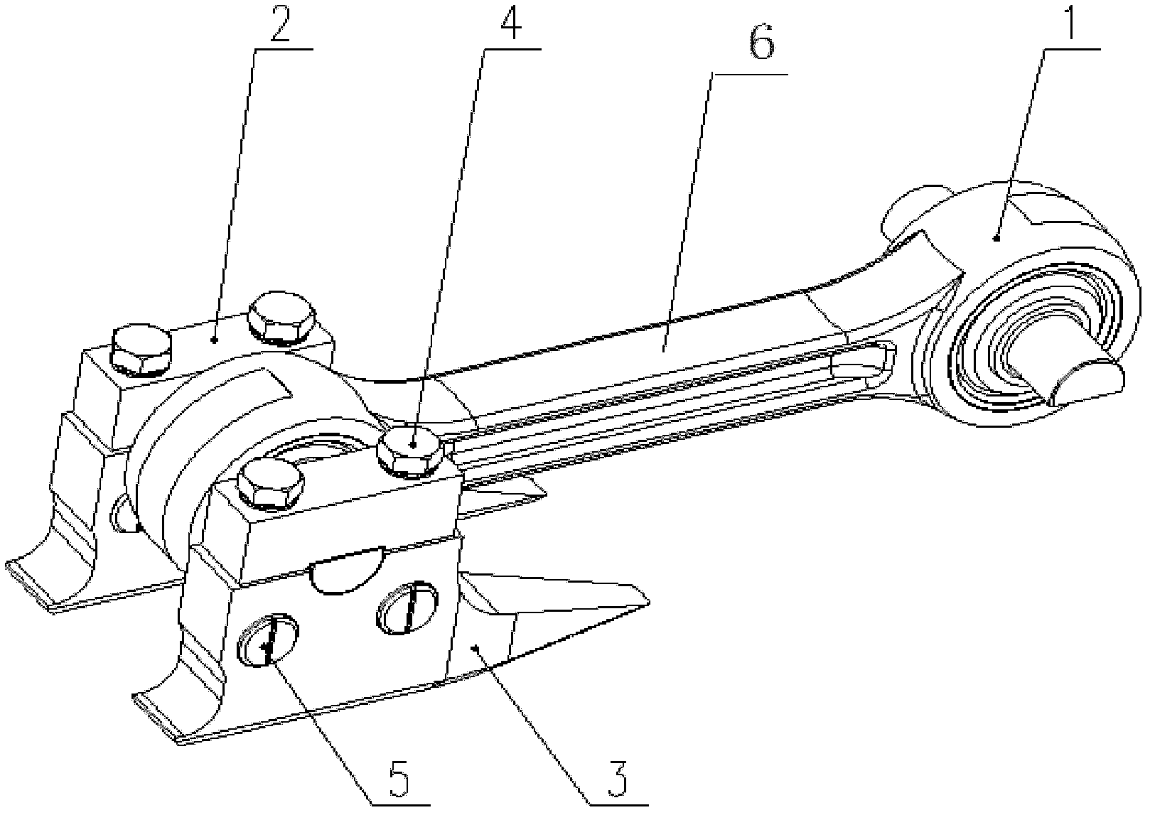
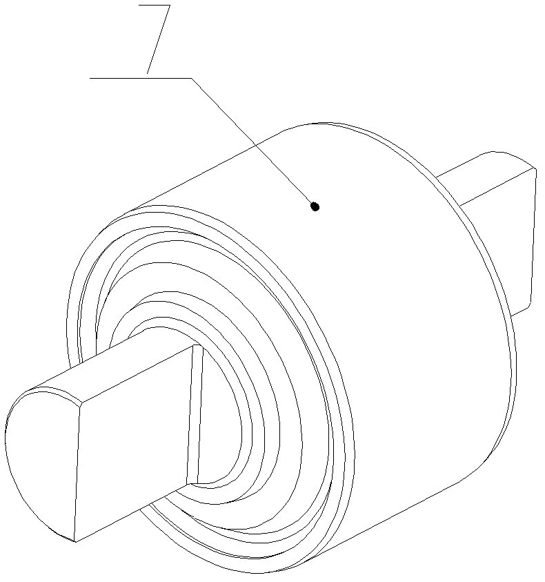
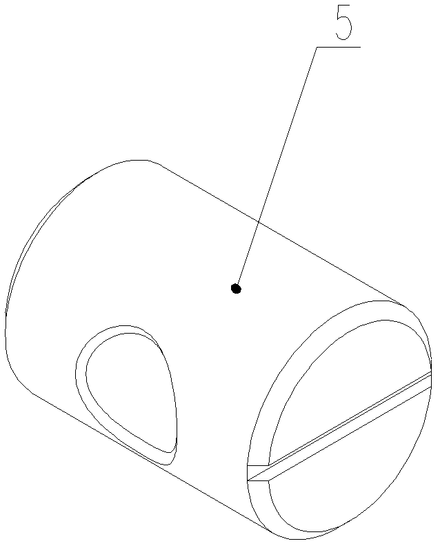
[0021] Traction tie rod devices for railway freight car bogies, such as figure 1 , figure 2 , image 3 As shown, it includes a traction rod assembly 1, an upper mount 2, a lower mount 3, four bolts 4, and four pin nuts 5. The traction rod assembly 1 includes a traction rod 6 and a rubber joint 7. The traction rod The two ends of 6 are circular holes, and the elastic rubber joint 7 is arranged in the circular hole of the traction rod 6, and the rubber joint 7 and the traction rod 6 adopt an interference fit. The traction rod assembly 1 is connected with the holes of the upper mounting base 2 and the lower mounting base 3 through the two ends of the rubber joint 7. The upper mounting base 2 and the lower mounting base 3 are connected by bolts 4 and nuts. The nuts are pin nuts 5 to prevent The upper mounting seat 2 and the lower mounting seat 3 cause e...


PUM


Abstract

The invention discloses a traction pull rod device of a railway wagon bogie. The traction pull rod device of the railway wagon bogie comprises a traction pull rod assembly, an upper mounting seat and a lower mounting seat, wherein the traction pull rod assembly comprises a traction pull rod and an elastic rubber joint; circular holes are formed at the two ends of the traction pull rod; the elastic rubber joint is arranged in the circular holes of the traction pull rod; the traction pull rod assembly is connected with holes of the upper mounting seat and the lower mounting seat through the two ends of the rubber joint in a matched way; the upper mounting seat is connected with the lower mounting seat by using a bolt and a nut; the two ends of the rubber joint are semi-cylindrical surfaces; the hole of the lower mounting seat is a semicircular hole; the hole of the upper mounting seat is a recess; the semicircular hole of the lower mounting seat corresponds to the recess of the upper mounting seat in position; and the semi-cylindrical surface matches with the semicircular hole of the lower mounting seat and the recess of the upper mounting seat. The traction pull rod device of the railway wagon bogie, disclosed by the invention, has the advantages of simple structure, convenience for maintenance, wear resistance, large longitudinal force transmission, reliable performance and suitability for large transverse displacement requirements between high-speed railway wagon main body and the bogie.

Description

technical field [0001] The invention relates to the technical field of steering of high-speed railway freight cars, in particular to a traction rod device of a railway freight car bogie. Background technique [0002] At present, the longitudinal force transmission of the integral frame bogie of railway freight cars is generally realized by the center plate, but when the high-speed freight car reaches the speed level of 200km / h, it must adopt the structural mode of full side bearing, and special structural design must be adopted at this time. Complete the transmission of the longitudinal force of the car body. [0003] Traditional passenger car bogies generally adopt a "Z"-shaped double traction rod or single rod structure, and the single structure mostly adopts a bolt-stressed structure. Due to its complex structure, double traction rods are not suitable for use on truck bogies, while single traction rod devices have the remarkable feature of simple structure, and are espec...

Claims


Application Information

Patent Timeline
IPC IPC(8): B61F5/50
Inventor 翟鹏军刘寅华刘红日王晋刚李晓伟
Owner CRRC SHANDONG CO LTD
Learn More