Check patentability & draft patents in minutes with Patsnap Eureka AI!

Cutting apparatus

A cutting device and cutting fluid technology, applied in the direction of fine working devices, electrical components, working accessories, etc., can solve the problem of insufficient fluidity of cutting fluid, and achieve the effects of good fluidity, reduction of gaps, and inhibition of clogging

Active Publication Date: 2012-07-04
DISCO CORP
View PDF7 Cites 2 Cited by
  • Summary
  • Abstract
  • Description
  • Claims
  • Application Information

AI Technical Summary

Problems solved by technology

[0007] However, in the cutting method described in Patent Document 1 above, since pure water to which ultrasonic vibrations are applied is supplied, the fluidity of the cutting fluid entering the cutting groove cut by the cutting tool is insufficient, and it is not necessarily possible to suit one's needs

Method used


Image

  • Cutting apparatus
  • Cutting apparatus
  • Cutting apparatus

Examples


Embodiment Construction

[0044] Next, preferred embodiments of the cutting device according to the present invention will be described in further detail with reference to the drawings.

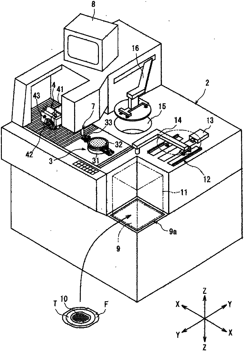
[0045] figure 1 A perspective view of a cutting device constructed by the present invention is shown. figure 1 The shown cutting device includes a substantially cuboid-shaped device housing 2 . In the device case 2, a chuck table 3 holding a workpiece is disposed so as to be movable in a direction indicated by an arrow X (X-axis direction) which is a cutting feed direction. The chuck table 3 includes a suction chuck support table 31 and a suction chuck 32 disposed on the suction chuck support table 31, and the workpiece is sucked and held on the suction chuck by operating a suction member (not shown). The upper surface of 32 promptly keeps on the face. In addition, the chuck table 3 is configured to be rotatable by a rotation mechanism not shown. In addition, a clamper 33 for fixing a ring-shaped frame supporting ...


PUM


Abstract

A cutting apparatus including a chuck table for holding a workpiece, a cutting unit having a cutting blade for cutting the workpiece held on the chuck table, a cutting water supplying unit for supplying a cutting water to a work portion to be cut by the cutting blade, a pair of vibrating plates provided on the opposite sides of the cutting blade in such a manner that a spacing for forming a cutting water layer is defined between the upper surface of the workpiece held on the chuck table and the lower surface of each vibrating plate, and an ultrasonic vibrator for giving ultrasonic vibration to the vibrating plates.

Description

technical field [0001] The present invention relates to a cutting device for cutting workpieces such as semiconductor wafers. Background technique [0002] In the manufacturing process of a semiconductor device, a plurality of regions are divided on the surface of a substantially disk-shaped semiconductor wafer by dividing lines called streets (streets) arranged in a grid pattern, and these divided regions are IC (Integrated Circuit: Integrated Circuit), LSI (Large Scale Integration: Large Scale Integrated Circuit) and other devices are formed in the process. Individual semiconductor devices are manufactured by cutting the thus-formed semiconductor wafer along the lanes to divide regions where the devices are formed. In addition, optical device wafers in which gallium nitride-based compound semiconductors are laminated on the surface of a sapphire substrate are also cut along the gaps, and are divided into optical devices such as light-emitting diodes and laser diodes one b...

Claims


Application Information

Patent Timeline
Patent Type & Authority Applications(China)
IPC IPC(8): B28D5/04B28D7/04H01L21/78
CPCB28D5/0076Y10T83/364
Inventor 邱晓明
Owner DISCO CORP
Features
  • R&D
  • Intellectual Property
  • Life Sciences
  • Materials
  • Tech Scout
  • Unparalleled Data Quality
  • Higher Quality Content
  • 60% Fewer Hallucinations
Learn More