Supercharge Your Innovation With Domain-Expert AI Agents!

Valve arrangements in particular in automatic transmissions of vehicles

A valve device and loading device technology, which is applied in the field of valve devices, can solve problems such as lasting for a long time, and achieve the effect of hydraulic pressure enhancement

Active Publication Date: 2016-12-14
ROBERT BOSCH GMBH
View PDF5 Cites 0 Cited by
  • Summary
  • Abstract
  • Description
  • Claims
  • Application Information

AI Technical Summary

Problems solved by technology

Without this brief over-energization, the gear change lasts a long time

Method used


Image

  • Valve arrangements in particular in automatic transmissions of vehicles
  • Valve arrangements in particular in automatic transmissions of vehicles
  • Valve arrangements in particular in automatic transmissions of vehicles

Examples


Embodiment Construction

[0028] For functionally equivalent elements and dimensions in all figures, the same reference signs are used even in different embodiments.

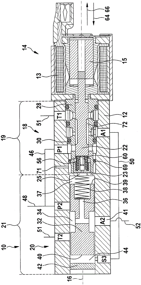
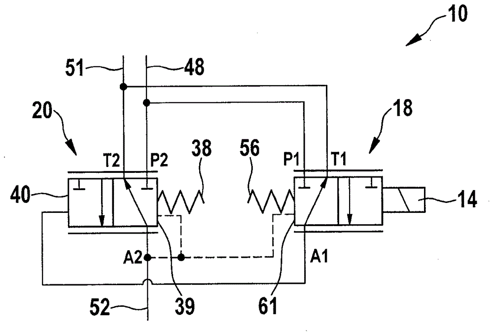
[0029] figure 1 A valve arrangement 10 for hydraulically operating a clutch arrangement or gear shifter of an automatic transmission of a vehicle is shown. The valve device 10 comprises a housing 12 designed as a so-called control panel, on which a triggerable actuating device 14 , here in the form of an electromagnet 14 , is arranged in the region on the right in the drawing. The electromagnet 14 includes a coil 13 and an armature 15 . Valve device 10 and the elements associated with valve device 10 are formed substantially rotationally symmetrically about longitudinal axis 16 .

[0030]Furthermore, the valve arrangement 10 comprises a pressure regulating valve 18 along a first valve section 19 in the middle area of ​​the drawing and a slide valve 20 along a second valve section 21 in the left area of ​​the drawing. The first valve s...


PUM


Abstract

The invention relates to a valve arrangement (10), in particular in an automatic transmission of a vehicle, having a first valve slide (22) of a pressure regulating valve (18) and a second valve slide (32) of a slide valve (20), The first spool is actuated by a triggerable actuating device (14), wherein the pressure regulating valve (18) regulates the operating pressure (41) of the slide valve (20).

Description

technical field [0001] The invention relates to a valve arrangement having a first valve element of a pressure regulating valve and a second valve element of a slide valve, the first valve element being acted upon by a triggerable actuating device. Background technique [0002] Transmissions or automatic transmissions for vehicles are known on the market, in which one or more transmission clutches or actuating cylinders for actuating the clutches are used. The individually activated clutches transmit the motor torque to the drive wheels. In order to be able to transmit a specific torque, the clutch plates of the individual clutches are pressed together with pressure. In order to achieve this pressure, the clutch plates must first be moved by a certain stroke. For this purpose - in hydraulic control - a certain amount of liquid or a certain hydraulic volume flow is required. Depending on the size of the clutch, the volume flow is approximately 3 to 10 l / min (liters per min...

Claims


Application Information

Patent Timeline
Patent Type & Authority Patents(China)
IPC IPC(8): F16H63/02F16K11/07F16K31/44
CPCF16H61/0251F16H2061/0253F16H2061/0258F16K31/0613F16K31/0686F16K2200/301F16K31/12F16H57/027
Inventor M-F.森C.奥特
Owner ROBERT BOSCH GMBH
Features
  • R&D
  • Intellectual Property
  • Life Sciences
  • Materials
  • Tech Scout
  • Unparalleled Data Quality
  • Higher Quality Content
  • 60% Fewer Hallucinations
Learn More