Unlock instant, AI-driven research and patent intelligence for your innovation.

Field-of-view splicing three-dimensional display image correction system and correction method

A technology of three-dimensional display and image correction, applied in stereo systems, image communication, optics, etc., can solve the problem that images cannot be displayed perfectly, and achieve the effect of improving image quality

Inactive Publication Date: 2015-09-02
ZHEJIANG UNIV
View PDF5 Cites 0 Cited by
  • Summary
  • Abstract
  • Description
  • Claims
  • Application Information

AI Technical Summary

Problems solved by technology

[0003] Usually, a successful 3D display device needs to comprehensively consider many aspects such as image resolution, 3D display effect, and computing cost. Currently, the stereoscopic 3D display devices that have been developed are limited by factors such as system structure, which often lead to images generated in theoretical conditions. It cannot be perfectly displayed, and it is more practical to seek an image correction system and method that comprehensively considers system imaging aberration and device accuracy.

Method used


Image

  • Field-of-view splicing three-dimensional display image correction system and correction method
  • Field-of-view splicing three-dimensional display image correction system and correction method
  • Field-of-view splicing three-dimensional display image correction system and correction method

Examples


Embodiment Construction

[0025] An embodiment of the present invention will be described below with reference to the accompanying drawings.

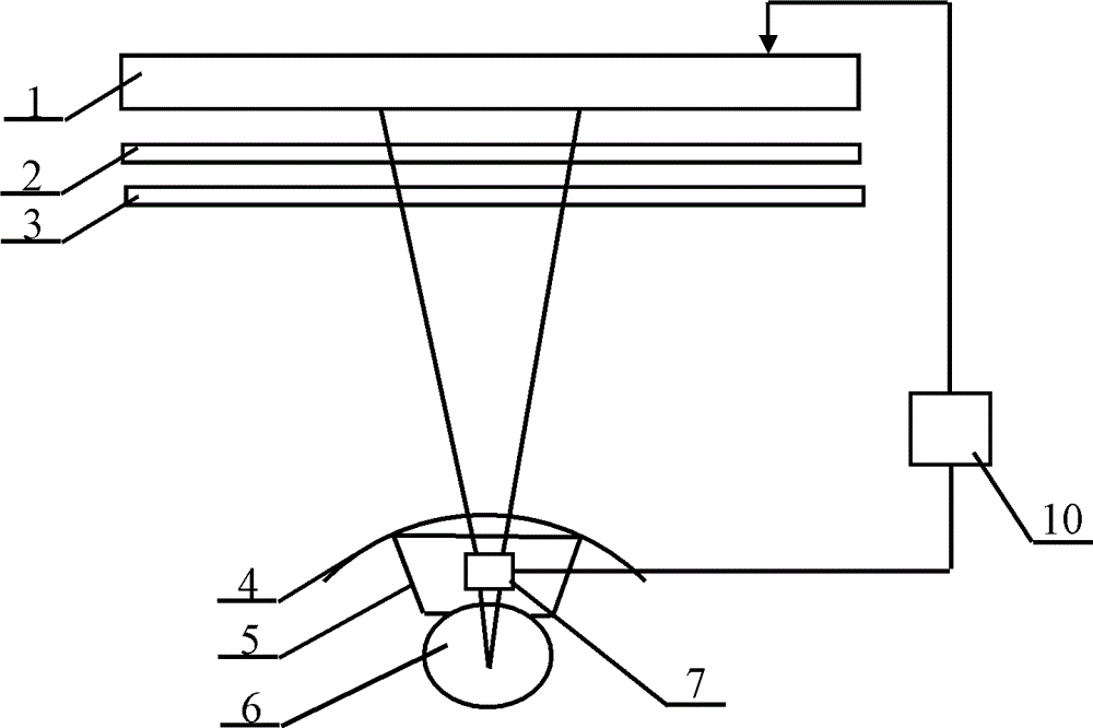
[0026] figure 1 It is a schematic diagram of the system structure of the present invention, figure 2 It is a sectional view of the system structure of the present invention. As shown in the figure, the field of view splicing three-dimensional display image correction system of the present invention includes a two-dimensional display unit array 1, a lens array 2, an aperture array 3, and an arc-shaped longitudinal scattering screen 4 arranged in sequence. 1. Plane beam splitter 5, arc longitudinal scattering screen 4 scatter light in longitudinal direction and not scatter light in horizontal direction, cylindrical diffuser 6 is arranged at the center of the arc where arc longitudinal scattering screen 4 is located, and, at the same horizontal height , the center of the circle obtained by the horizontal section of the cylindrical diffuser 6 coincides with the ce...


PUM


Abstract

The invention discloses a field-butting three-dimensional display image correction system, comprising a two-dimensional display unit array, a lens array, a diaphragm array, an arc-shaped longitudinal scattering screen, a planar splitting mirror, a cylindrical diffuser, an image collection component and an image treatment component, wherein the above parts are sequentially arranged. The image displayed by the two-dimensional display unit array passes through the lens array and the diaphragm array and then projected on the same position of the arc-shaped longitudinal scattering screen, and images are formed on the other side of the arc-shaped longitudinal scattering screen; the cylindrical diffuser is arranged in the circle center of the arc-shaped longitudinal scattering screen; imaging beams are scattered to the planar splitting mirror via the cylindrical diffuser and then reflected to the image collection component via the planar splitting mirror; the image treatment component is connected between the image collection component and the two-dimensional display unit array and used for finally treating the image collected by the image collection component. The invention further discloses a field-butting three-dimensional display image correction method.

Description

technical field [0001] The invention relates to an image correction system and correction method, in particular to a three-dimensional correction system and correction method for field of view splicing. Background technique [0002] Image correction technology has always been a research hotspot in the field of computer vision and image processing. With the rapid development of 3D panoramic display technology, image correction of 3D display systems through point-to-point mapping and camera acquisition is the main method currently used. Most of the existing stereoscopic 3D display devices provide enough viewing angles by splicing the field of view horizontally or vertically, allowing the observer's two eyes to span different viewing angles to obtain a delicate 3D perception. According to this principle, the image information reproduced on the 2D display system is related to the specific viewing angle design parameters of the 3D display device, and often needs to go through an ...

Claims


Application Information

Patent Timeline
Patent Type & Authority Patents(China)
IPC IPC(8): H04N13/04G02B27/26G02B30/25
Inventor 李海峰彭祎帆刘旭钟擎
Owner ZHEJIANG UNIV