Cab of engineering machine
A technology for construction machinery and cabs, applied in the field of cabs, can solve problems such as high welding quality requirements and high costs, and achieve the effects of low manufacturing difficulty, saving steel, and reducing manufacturing costs
- Summary
- Abstract
- Description
- Claims
- Application Information
AI Technical Summary
Problems solved by technology
Method used
Image

Examples
Example Embodiment
[0022] Example 1:
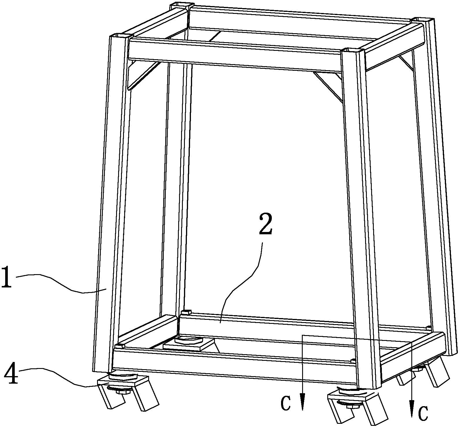
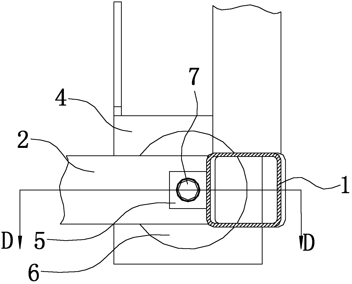
[0023] Figure 1 to Figure 3 The first embodiment of the present invention is shown. figure 1 Shown is the cab frame, that is, ROPS includes four uprights 1. The four uprights 1 are connected by four crossbeams at their upper and lower parts, and one of the lower crossbeams 2 of each upright 1 is provided with a through the lower crossbeam 2 The square through hole of beam 2, such as figure 2 image 3 As shown, a square mounting shaft 5 is arranged in the through hole. The upper and lower ends of the square mounting shaft 5 are welded to the lower cross beam 2. A hole is provided in the center of the lower end surface of the mounting shaft 5, and the hole wall is tapped with threads. When the cab is connected to the frame for installation, place the cab on the cab mounting seat 4, and the cab mounting bolts 7 from below the cab mounting support 4 go up through the mounting holes on the cab mounting support 4 and The mounting shaft 5 on the lower cross beam 2 ...
Example Embodiment
[0025] Example 2:
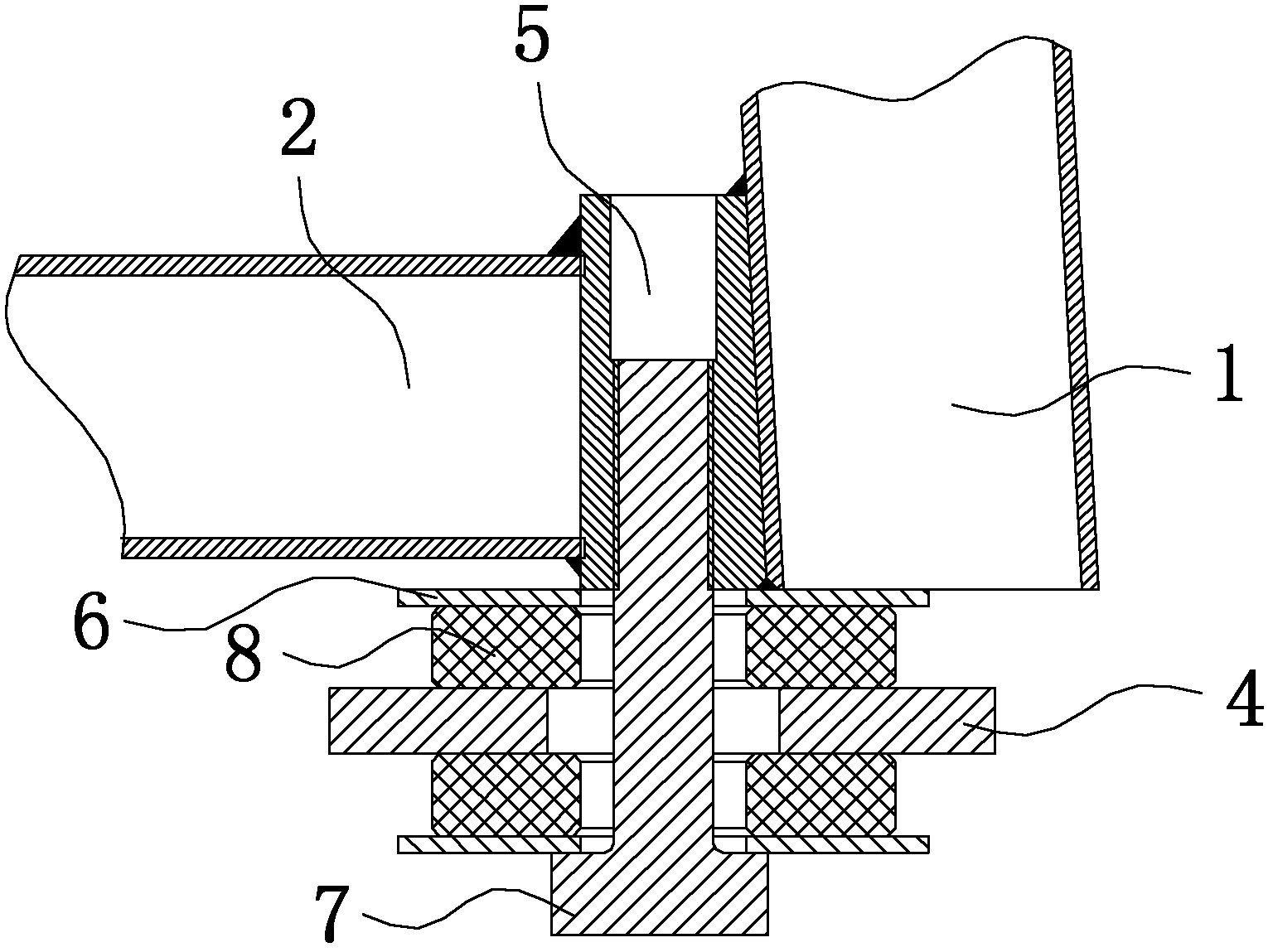
[0026] Figure 4 to Figure 5 The second embodiment of the present invention is shown. Such as Figure 4 As shown, the cab framework or ROPS includes four uprights 1. The four uprights 1 are connected by four crossbeams at the upper and lower parts of the four uprights. The connection between each of the uprights 1 and one of the lower crossbeams 2 is U-shaped. Slotted reinforcing plate 3, a circular through hole is provided on the lower cross beam 2 at a position below the U-shaped grooved reinforcing plate 3, and a round steel pipe is provided in the through hole to make a mounting shaft 5, such as Figure 5 As shown, the upper and lower ends of the mounting shaft 5 are welded to the lower cross beam 2, and the inner hole wall of the mounting shaft 5 is tapped with threads. A circular backing plate 6 is provided at the lower end of the installation shaft so as to be in full-area contact with the cab shock absorber 8 when the cab is installed. When the cab is...
Example Embodiment
[0027] Example 3:
[0028] Figure 6 to Figure 7 The third embodiment of the present invention is shown. Such as Image 6 As shown, the cab framework or ROPS includes four uprights 1. The four uprights 1 are connected by four crossbeams at the upper and lower parts. Crossbeams are provided at the roots of each upright 1, that is, where the two lower crossbeams 2 are adjacent to each other. The connecting reinforcement plate 9 connects the two adjacent lower beams, and a circular through hole is provided on the beam connecting reinforcement plate 9, such as Figure 7 As shown, a mounting shaft 5 made of round steel pipes is provided in the through hole. The upper and lower ends of the mounting shaft 5 are welded to the beam connecting reinforcing plate 9 and the inner hole wall of the mounting shaft 5 is tapped with threads to strengthen the installation The shaft 5 is connected with the beam connecting reinforcement plate 9, and an annular convex ring is provided on the outer si...
PUM
 Abstract
Description
Claims
Application Information
 - R&D Engineer
- R&D Manager
- IP Professional
- Industry Leading Data Capabilities
- Powerful AI technology
- Patent DNA Extraction
Browse by: Latest US Patents, China's latest patents, Technical Efficacy Thesaurus, Application Domain, Technology Topic.
© 2024 PatSnap. All rights reserved.Legal|Privacy policy|Modern Slavery Act Transparency Statement|Sitemap