Check patentability & draft patents in minutes with Patsnap Eureka AI!

Vehicle motion control device

A motion control device and braking control technology, applied in the direction of brakes, etc., can solve the problems of deterioration of followability and bad feeling of the driver, and achieve the effect of good following performance, restraining the reduction of lateral force, and restraining rollover.

Active Publication Date: 2012-08-01
ADVICS CO LTD
View PDF4 Cites 5 Cited by
  • Summary
  • Abstract
  • Description
  • Claims
  • Application Information

AI Technical Summary

Problems solved by technology

[0005] However, in the technique disclosed in Patent Document 1, the rollover of the vehicle body is prevented by causing the outer wheel in the turning direction to slip in the direction of centrifugal force, so the wheel will travel along the driver's undesired route, resulting in a tendency to follow. deterioration
Therefore, there is fear of giving the driver a bad feeling

Method used


Image

  • Vehicle motion control device
  • Vehicle motion control device
  • Vehicle motion control device

Examples


Embodiment Construction

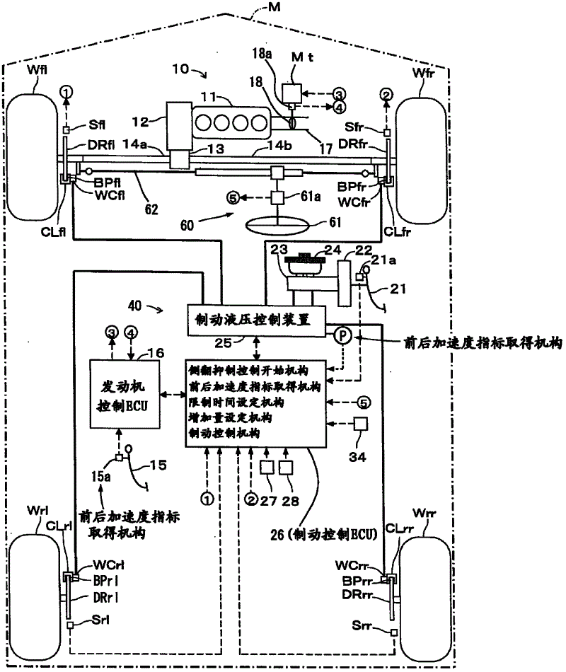
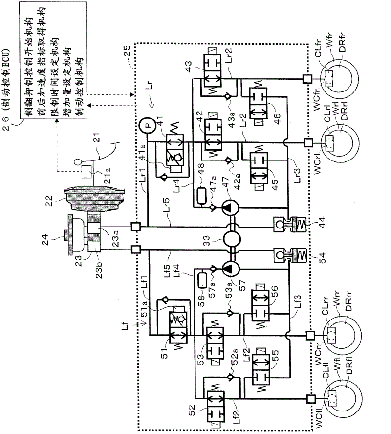
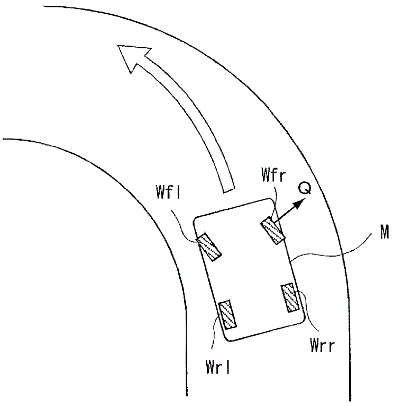
[0026] Hereinafter, a first embodiment of a vehicle using the motion control device according to the present invention will be described with reference to the drawings. The motion control device is a device that applies a braking force to the turning outside front wheel and the turning outside rear wheel of the vehicle to suppress rollover of the vehicle. In addition, here, the turning outside front wheel refers to the front wheel on the side away from the turning center of the vehicle among the two front wheels Wfl and Wfr of the vehicle. In addition, the turning outside rear wheel refers to the rear wheel on the side away from the turning center of the vehicle among the two rear wheels Wrl, Wrr of the vehicle.

[0027] figure 1 It is a schematic diagram showing the structure of the vehicle. The vehicle M is a front-wheel drive (FF) vehicle in which the driving force of the engine 11, which is a driving source mounted on the front of the vehicle body, is transmitted to the ...


PUM


Abstract

The invention provides a motion control device, which, with a simple structure, can achieve good tracking performance during rollover prevention control of vehicles. The motion control device, which performs rollover prevention control to avoid rollover of a vehicle (M) by applying a braking force on the front wheel at the steering outer side and the rear wheel at the steering outer side of the vehicle, has a brake control mechanism (26). When a braking force (P) is applied to the front wheel at the steering outer side and the rear wheel at the steering outer side as the rollover prevention control, the brake control device (26) limits the application of the braking force on the front wheel at the steering outer side until a predetermined time elapses since the beginning of the application of the braking force on the rear wall at the steering outer side.

Description

technical field [0001] The present invention relates to a motion control device that controls the motion of a turning vehicle by controlling the braking force applied to the wheels. Background technique [0002] Conventionally, when the vehicle is turning, it is required to control the motion of the vehicle so that the vehicle does not roll over due to excessive roll produced on the vehicle. Usually, the size of the roll depends on the component of the acceleration acting on the vehicle in the left and right directions of the vehicle body, that is, the actual lateral acceleration (that is, the centrifugal force acting on the vehicle), which will change with the increase of the actual lateral acceleration. big. [0003] Therefore, for example, in the braking device of a vehicle described in Patent Document 1, a rollover prevention threshold is set using actual lateral acceleration, etc. indicating a rollover situation as an index, and when the (absolute value of) the actual ...

Claims


Application Information

Patent Timeline
IPC IPC(8): B60T8/1755B60T8/26B60T8/32
CPCB60T8/17554B60T8/243
Inventor 山田哲也古藤英章
Owner ADVICS CO LTD
Features
  • R&D
  • Intellectual Property
  • Life Sciences
  • Materials
  • Tech Scout
  • Unparalleled Data Quality
  • Higher Quality Content
  • 60% Fewer Hallucinations
Learn More