
Grounding sleeve of generator rotor

A generator, bushing technology, applied in electrical components, circuit devices, emergency protection circuit devices for limiting overcurrent/overvoltage, etc., can solve problems such as short circuit, damage to rectifier components, and diode reverse bias damage

Active Publication Date: 2012-08-01
HAMILTON SUNDSTRAND CORP
View PDF4 Cites 0 Cited by
  • Summary
  • Abstract
  • Description
  • Claims
  • Application Information

AI Technical Summary

Problems solved by technology

When the voltage exceeds the avalanche voltage characteristic of the silicone die, the reverse bias on the diode is destroyed and shorted, thus damaging the rectifying components

Method used


Image

  • Grounding sleeve of generator rotor
  • Grounding sleeve of generator rotor
  • Grounding sleeve of generator rotor

Examples


Embodiment Construction

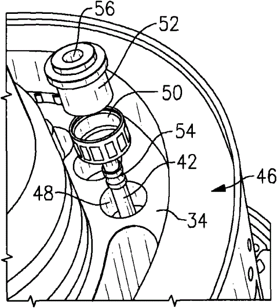
[0010] figure 1 Generators 10 of the type shown are commonly used in aerospace applications. The generator 10 includes main, field and permanent magnet generator (PMG) components 14 , 16 , 18 . In one embodiment, the main, field and PMG components 14 , 16 , 18 include first, second (field) and third rotors 22 , 24 , 26 , respectively, supported by a common shaft 20 rotatable about axis A, respectively. During rotation, the first, second and third rotors 22, 24, 26 respectively cooperate with the first, second and third stators 28, 30, 32 to rotate each of the main, field and PMG components 14, 16, 18. An alternating current is generated in one.

[0011] figure 2 The field rotor 24 is schematically depicted. The field rotor 24 includes a rotor frame 34 that supports a rotor circuit 35 . The field armature coil 38 in the rotor circuit 35 induces an alternating current through the rectification means 36 . The diode 40 in the rectifying section 36 rectifies the alternating ...


PUM


Abstract

The invention relates to a grounding sleeve of a generator rotor. A generator comprises a rotor structure which comprises a rotor framework supporting a magnetic field coil and a rectification part. The rotor framework comprises an aperture, and a bus passes through the aperture and electrically connects the magnetic field coil to the rectification part. The grounding sleeve electrically connects the bus to the rotor framework.

Description

technical field [0001] The invention relates to a generator rotor and a rotor circuit thereof. Background technique [0002] The generator includes a stator fixed relative to the casing and a rotor rotatable about an axis relative to the stator. The rotor includes a rotor frame that supports a rotor circuit including field coils and rectifying components with diodes. The rotation of the rotor relative to the stator induces an alternating current in the field coils, which is converted into a DC voltage by means of a rectifier. [0003] Generators can experience rectifier component failures due to damaged diodes. One failure mode is produced by an electrostatic discharge event from the rotor frame to the isolated rotor circuit. Typically, the rotor frame has holes through which the busbars pass. The busbars, electrically connected to the rotor circuit, are electrically insulated from the rotor frame by insulating bushings. The isolated rotor circuit establishes a high vol...

Claims


Application Information

Patent Timeline
Patent Type & Authority Applications(China)
IPC IPC(8): H02K1/22H02K1/28H02H9/04
Inventor N·A·贝里
Owner HAMILTON SUNDSTRAND CORP
Learn More