Supercharge Your Innovation With Domain-Expert AI Agents!

Variable nozzle ring positioning structure

A positioning structure and nozzle ring technology, applied in the direction of engine components, machines/engines, mechanical equipment, etc., can solve the problems of low efficiency, large number of parts installed, poor versatility, etc., and achieve high efficiency, strong versatility of parts, and easy operation Effect

Active Publication Date: 2015-05-20
HUNAN TYEN MACHINERY
View PDF6 Cites 0 Cited by
  • Summary
  • Abstract
  • Description
  • Claims
  • Application Information

AI Technical Summary

Problems solved by technology

[0005] The above structure has the following deficiencies: one is that the number of parts installed is large and the efficiency is low; the other is that this installation method determines that the installation angle of the turbine box and the bearing body must be unique. If the installation angle of the turbo end of the turbocharger changes, the Newly designed turbine box, poor versatility

Method used


Image

  • Variable nozzle ring positioning structure
  • Variable nozzle ring positioning structure
  • Variable nozzle ring positioning structure

Examples


Embodiment Construction

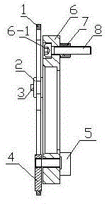
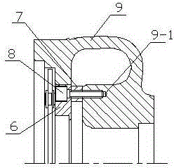
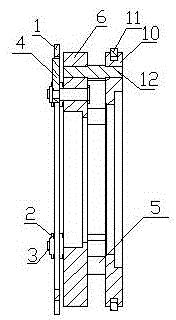
[0020] A variable nozzle ring positioning structure, which is to change the three countersunk screw mounting holes 6-1 on the blade seat 6 of the existing variable nozzle into three pin holes 6-2, and cancel the three countersunk screws 8 and three distance sleeves 7, then increase a disc-shaped back cover 10. The disc-shaped back cover 10 is provided with an annular groove 10-1 for installing a positioning retaining ring 11 on the radially outer circle, and the positioning retaining ring 11 is installed in the annular groove 10-1 on the outer circle of the disc-shaped rear cover 10, Three pin holes 10 - 2 are provided on the end surface of the disc-shaped rear cover 10 , and the three pin holes 10 - 2 are evenly distributed on the end surface of the disc-shaped rear cover 10 . The blade base 6 is connected with the disc-shaped back cover 10 through three step pins 12, one end of the step pin 12 and the pin hole 6-2 on the blade base 6 adopt an interference fit, and the other ...


PUM


Abstract

Disclosed is a variable nozzle ring positioning structure. Three dowel holes are arranged on an existing variable nozzle ring seat instead of sunk screw mounting holes, three sunk screws and three distance sleeves are omitted, and the variable nozzle ring positioning structure is additionally provided with a disc-shaped rear cover. An annular groove for mounting a positioning check ring is arranged on an outer circle of the disc-shaped rear cover, the positioning check ring is mounted in the annular groove, the three dowel holes are arranged on an end surface of the disc-shaped rear cover, blade seats are integrally connected with the disc-shaped rear cover by three stepped dowels, three threaded holes for mounting a variable nozzle in a turbine box at present are omitted, an annular cavity is arranged on an end surface in the turbine box, the variable nozzle is mounted on the end surface in the turbine box, and the annular groove for mounting the positioning check ring is arranged on the inner wall of the annular cavity. During installation, the disc-shaped rear cover on the variable nozzle is mounted in the annular cavity of the turbine box, the positioning check ring mounted on the disc-shaped rear cover is simultaneously clamped into the annular groove in the annular cavity of the turbine box, and the variable nozzle is mounted in the turbine box via the positioning check ring.

Description

technical field [0001] The invention relates to the technical field of turbochargers, in particular to a variable nozzle ring positioning structure of a turbocharger. Background technique [0002] Turbocharging technology is an important means to meet the low fuel consumption, low emission and high power density of vehicle engines. With the increasingly stringent emission regulations, the use of variable nozzle turbocharging is an effective technical measure to meet the National III, National IV and higher emission standards. [0003] The principle of variable nozzle technology is that the adjustable blades rotate around their respective axes. With the change of the blade angle, the minimum flow cross-sectional area of ​​the turbine and the angle and speed of the exhaust gas entering the turbine will all change, thus changing the turbine's flow rate. speed and boost pressure at the outlet of the compressor. [0004] The existing variable nozzle is composed of a drive ring...

Claims


Application Information

Patent Timeline
Patent Type & Authority Patents(China)
IPC IPC(8): F01D17/16
Inventor 潘航宇潘伟刘麟周峥胡奇
Owner HUNAN TYEN MACHINERY
Features
  • R&D
  • Intellectual Property
  • Life Sciences
  • Materials
  • Tech Scout
  • Unparalleled Data Quality
  • Higher Quality Content
  • 60% Fewer Hallucinations
Learn More