Supercharge Your Innovation With Domain-Expert AI Agents!

Metal mould rotary injection molding machine and rotation method of rotating table thereof

A technology of a rotary table and an injection molding machine, which is applied in the field of rotation of a metal mold rotary injection molding machine and its rotary table, can solve the problem that the rotation of the rotary table cannot be stabilized, the sleeve and the bearing are partially worn or damaged, and Problems such as high friction resistance

Active Publication Date: 2012-09-19
JAPAN STEEL WORKS LTD
View PDF8 Cites 0 Cited by
  • Summary
  • Abstract
  • Description
  • Claims
  • Application Information

AI Technical Summary

Problems solved by technology

[0013] As described above, in Patent Document 1 to Patent Document 5, there is a possibility that the rotary table cannot be rotated stably.
That is, although Patent Document 1 to Patent Document 5 have a partition mechanism for the rotary table, they do not have a mechanism to limit the advance limit of the rotary table, or even if they have a structure that uses a spring or a structure formed on a part of the rotary shaft, so The table may shake during the rotation of the rotary table
In addition, if the table is shaken during the rotation of the rotary table, as a result, the sleeve and the bearing between the movable plate and the rotating shaft of the rotary table may be partially worn or damaged during long-term use. more sexual
In addition, in Patent Document 4, when the rotary table is rotated, the pressing member and the member for partition contact from the upper surface side and the lower surface side of the table, but since they are in surface contact, the frictional resistance is low. Big

Method used


Image

  • Metal mould rotary injection molding machine and rotation method of rotating table thereof
  • Metal mould rotary injection molding machine and rotation method of rotating table thereof
  • Metal mould rotary injection molding machine and rotation method of rotating table thereof

Examples


Embodiment Construction

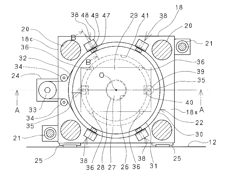
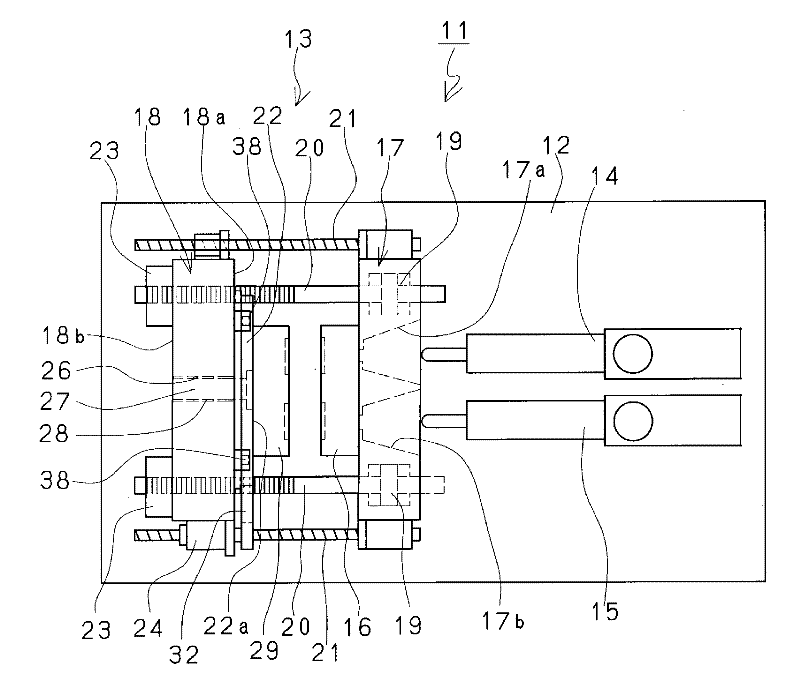
[0026] refer to figure 1 The outline of the mold rotary injection molding machine according to the embodiment of the present invention will be described. The mold rotary injection molding machine 11 basically includes a mold clamping device 13 provided on one side of a base 12 and injection devices 14 and 15 provided on the other side. The injection devices 14 and 15 are well known, and two injection devices are provided side by side for the purpose of injecting different materials, respectively. In addition, the configuration of the injection device is not limited to figure 1 In the illustrated structure, one injection device may be provided next to the mold clamping device, or a structure may have three or more injection devices.

[0027] In the description of the horizontal mold clamping device 13 , the fixed plate 17 on which the metal mold 16 is mounted is fixedly disposed on the base 12 . Furthermore, a movable platen 18 is disposed on the base 12 on the side (anti-...


PUM


Abstract

Provided are a metal mould rotary injection molding machine which uses a relative simple structure to confine a forwarding limit of a rotating table, wherein an outer side of the rotary table does not swing but rotates stably, and a rotation method of a rotating table thereof. A fixing disk (17) or a movable disk (18) is rotatably and separately arranged in a metal mould rotary injection molding machine (11) provided with a rotating table (22) of a rotating metal mould (29); a separation restriction mechanism (38) for restricting the separation of the a rotating table (22) is arranged on an part except the part of a rotating shaft (27) of the rotating table (22) against which the disks are abutted. The separation restriction mechanism (38) is provided with a rolling mechanism (47) for abutting against the rotating table (22).

Description

technical field [0001] The present invention relates to a rotary mold injection molding machine in which a rotary table on which a rotary mold is mounted is rotatably and separably provided on one of a fixed disk and a movable disk, and the rotation of the rotary table of the rotary mold injection molding machine method. Background technique [0002] With regard to a rotary mold injection molding machine in which a rotary table on which a rotary mold is mounted is rotatably and detachably provided to one of the fixed disk and the movable disk, there is known an upper movable disk of a vertical mold clamping device. Patent Document 1 with a rotary table, Patent Document 2 with a rotary table on the lower fixed plate of the vertical mold clamping device, and Patent Document 3 with a rotary table on the movable plate of the horizontal mold clamping device , Patent Document 4, and Patent Document 5 in which a rotary table is provided on a fixed plate of a horizontal mold clampi...

Claims


Application Information

Patent Timeline
Patent Type & Authority Applications(China)
IPC IPC(8): B29C45/06B29C45/10
Inventor 宫木毅三塚敏文
Owner JAPAN STEEL WORKS LTD
Features
  • R&D
  • Intellectual Property
  • Life Sciences
  • Materials
  • Tech Scout
  • Unparalleled Data Quality
  • Higher Quality Content
  • 60% Fewer Hallucinations
Learn More