Installation method of solar device integrated with building

A technology of solar energy devices and installation methods, which is applied in the direction of architecture, sustainable buildings, building structures, etc., can solve the problems of consuming manpower and material resources, complex construction methods, and affecting the orderliness and appearance of buildings, and achieve the advantages of convenient operation and beautiful appearance Effect

Inactive Publication Date: 2012-09-19
广州市晖源节能科技有限公司
View PDF7 Cites 3 Cited by
  • Summary
  • Abstract
  • Description
  • Claims
  • Application Information

AI Technical Summary

Problems solved by technology

[0002] The traditional method of installing solar energy devices is to install brackets and heat collectors on the roof to obtain solar energy. The disadvantages of this installation method are: firstly, it will seriously affect the neatness and beauty of the building, the installation is complicated, the installation site is limited, and the installation In the process, it is impossible to reduce the investment in the building itself, or even increase the investment, and the installation process and the pressure of the bracket are easy to damage the roof waterproof layer, corrosion of the bracket and other reasons will cause safety problems; therefore, to solve this problem, it is necessary to integrate solar energy with the building to achieve, but the existing solar roof is still very rare, because the common construction method is very complicated
First of all, when building a solar roof, it is necessary to open a mold that matches the solar device, and th

Method used


Image

  • Installation method of solar device integrated with building
  • Installation method of solar device integrated with building
  • Installation method of solar device integrated with building

Examples


Embodiment Construction

[0011] The present invention will be further described below in conjunction with the accompanying drawings and embodiments.

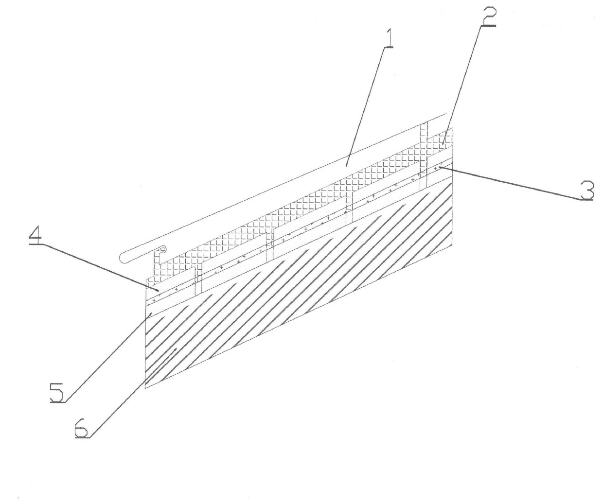
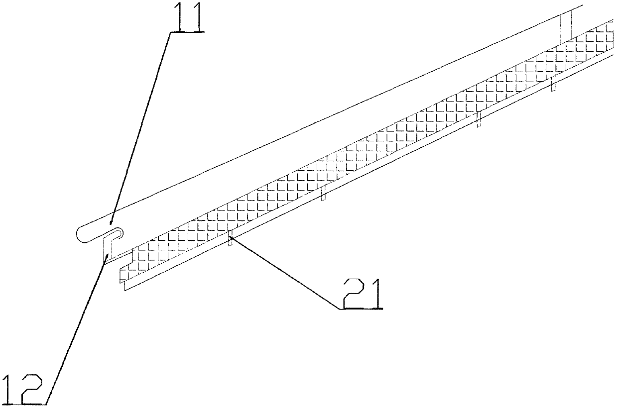
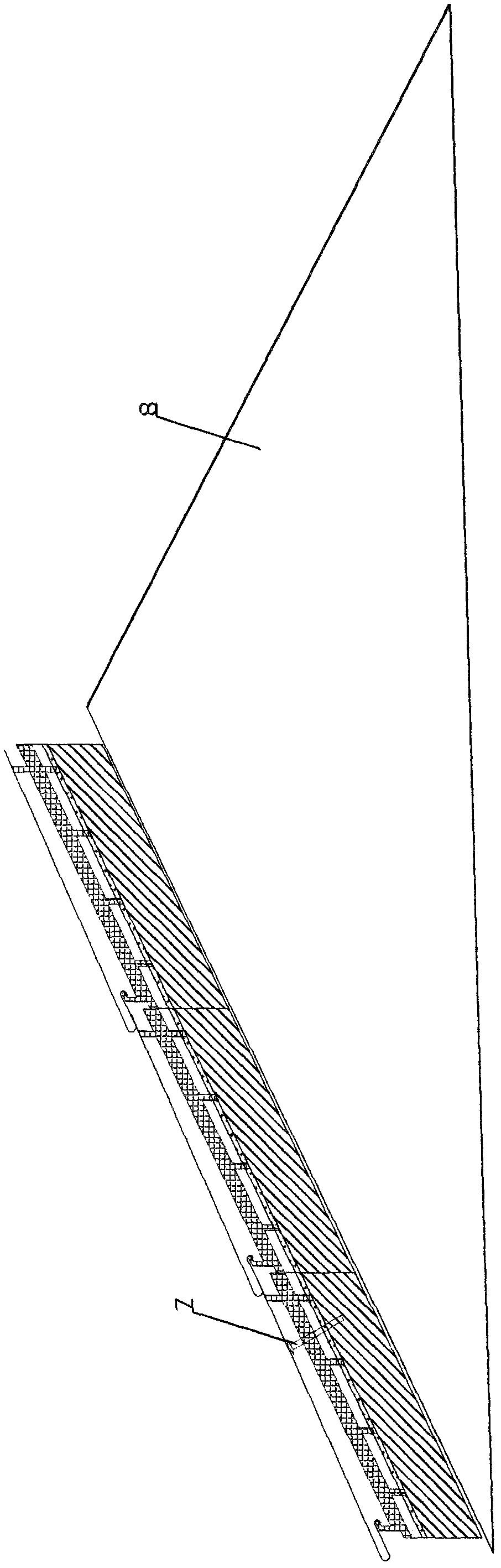
[0012] see Figure 1 to Figure 3 , a building-integrated solar device installation method, using anchors 7 and cement sand to bond and hang the solar structure board on any angle of the building surface 8; wherein: the solar structure is a module unit, and the module unit Designed in the shape of glazed tiles or exterior wall tiles, it can be spliced ​​and formed according to the size and shape of the building during use; the solar structural panel is composed of a light-transmitting layer 1, an upper insulation layer 4, a heat-absorbing layer 2, a conduit layer 3 and The heat storage layer and the lower insulation layer 5 are integrally formed by welding; while the building is being constructed, the anchors 7 and cement sand are used to install them on the building synchronously, and the above-mentioned functions of waterproof and heat insulation; 1 e...


PUM

PropertyMeasurementUnit
Thicknessaaaaaaaaaa

Abstract

The invention relates to an installation method of solar device integrated with building. Anchoring parts and cement mortar are used for bonding and hanging a solar structural panel at any angle of a building surface, wherein the solar structural panel consists of modular units, the modular units are designed to be glazed-tile-shaped or external-wall-tile-shaped and the modular units can be spliced together according to the area and the shape of a building during use; and the solar structural panel consists of a transparent layer, an upper heat insulation layer, a heat absorbing layer, a guide tube layer, a heat storage layer and a lower heat insulation layer which are integrally welded. When the building is constructed, the solar structural panel is synchronously installed on the building by using the anchoring parts and the cement mortar to take waterproof and heat insulation functions. A groove is arranged at one end of the transparent layer. One end of the heat absorbing layer is raised to form an inverted-L-shaped fastener which is matched with the mouth of the groove. The other end of the transparent layer is L-shaped. A plurality of columnar fasteners are distributed at the lower end of the heat absorbing layer, penetrate through the upper heat insulation layer, the heat absorbing layer, the guide tube layer and the heat storage layer and are connected with the lower heat insulation layer.

Description

technical field [0001] The invention relates to a method for applying solar energy, in particular to a method for installing a building-integrated solar energy device. Background technique [0002] The traditional method of installing solar energy devices is to install brackets and heat collectors on the roof to obtain solar energy. The disadvantages of this installation method are: firstly, it will seriously affect the neatness and beauty of the building, the installation is complicated, the installation site is limited, and the installation In the process, it is impossible to reduce the investment in the building itself, or even increase the investment, and the installation process and the pressure of the bracket are easy to damage the roof waterproof layer, corrosion of the bracket and other reasons will cause safety problems; therefore, to solve this problem, it is necessary to integrate solar energy with the building To achieve, but the existing solar roof is still very...

Claims


Application Information

Patent Timeline
IPC IPC(8): E04G21/14E04D13/18
CPCY02B10/20
Inventor 颜标兵
Owner 广州市晖源节能科技有限公司
Why Eureka
Try Eureka