Check patentability & draft patents in minutes with Patsnap Eureka AI!

Illumination system, lithographic apparatus and illumination method

A technology of irradiation system and lithography equipment, which is applied in the field of irradiation system, and can solve the problem that the first irradiation mode cannot be modified.

Inactive Publication Date: 2012-09-26
ASML NETHERLANDS BV
View PDF5 Cites 4 Cited by
  • Summary
  • Abstract
  • Description
  • Claims
  • Application Information

AI Technical Summary

Problems solved by technology

[0013] This arrangement has the disadvantage that it cannot modify the first illumination pattern simply by having a field facet not illuminate its associated first pupil facet without causing the field facet to illuminate its associated second pupil facet
Similarly, it is not possible to modify the second illumination pattern by having the field facet not illuminate the second pupil facet without having the field facet illuminate the first pupil facet

Method used


Image

  • Illumination system, lithographic apparatus and illumination method
  • Illumination system, lithographic apparatus and illumination method
  • Illumination system, lithographic apparatus and illumination method

Examples


Embodiment Construction

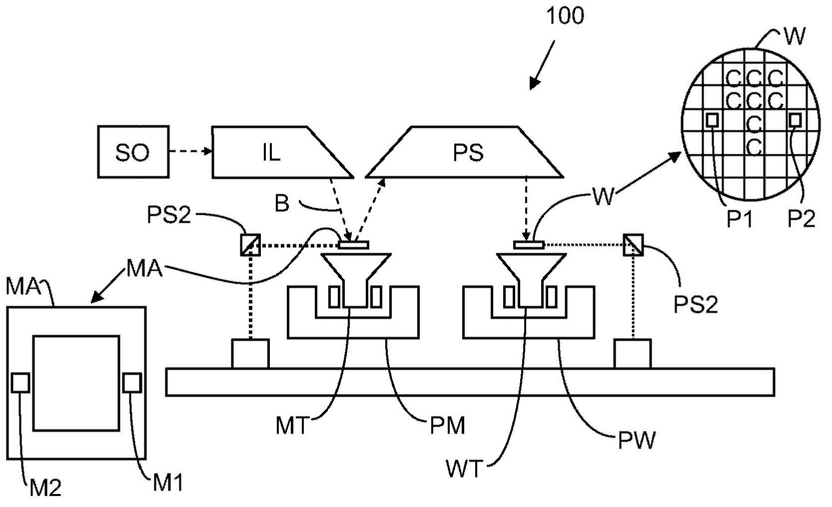
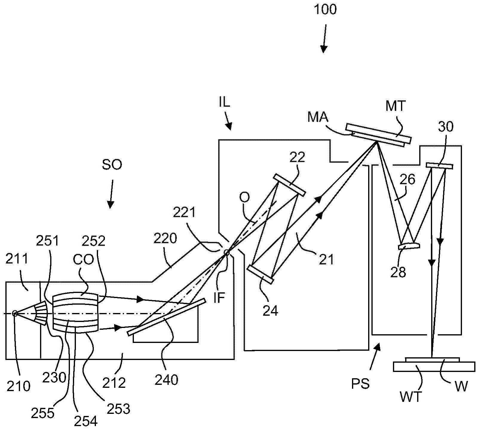
[0029] figure 1 A lithographic apparatus 100 comprising a source collector module SO according to an embodiment of the present invention is schematically shown. The apparatus comprises: an illumination system (illuminator) IL configured to condition a radiation beam B (e.g. EUV radiation); a support structure (e.g. a mask table) MT configured to support a patterning device (e.g. a mask or reticle) MA, and Connected to a first positioning device PM configured for precisely positioning the patterning device; a substrate table (e.g., a wafer table) WT configured to hold a substrate (e.g., a resist-coated wafer) W, and associated with A second positioning device PW configured for precisely positioning the substrate table; and a projection system (e.g. a reflective projection system) PS configured for projecting the pattern imparted to the radiation beam B by the patterning device MA onto the substrate W on target portion C (eg, including one or more dies).

[0030] The illuminat...


PUM


Abstract

An illumination system includes a field-facet mirror-device and a pupil mirror configured to condition a beam of radiation incident on the field-facet mirror-device. The field-facet mirror-device includes reflective field facets movable between first and second orientations relative to the incident beam. The field facets in their first orientations are effective to reflect the incident radiation towards respective reflective pupil facets so as to form part of a conditioned beam reflected from the pupil-facet mirror-device. The field facets in their second orientations are effective to reflect the incident radiation onto respective areas of the pupil-facet mirror-device designated as beam dump areas. The areas are arranged to prevent radiation incident on the areas from forming part of the conditioned beam and are arranged between the limits of an annular area on the pupil-facet mirror-device effective to define the inner and outer regions of the conditioned beam reflected from the pupil-facet mirror-device.

Description

[0001] Cross References to Related Applications [0002] This application claims priority to US Provisional Application 61 / 290,533, filed December 29, 2009, which is hereby incorporated by reference in its entirety. technical field [0003] The present invention generally relates to a lithographic apparatus. The invention finds particular application in illumination systems forming part of a lithographic apparatus and in particular, but not exclusively, in illumination systems for adjusting the profile of an extreme ultraviolet (EUV) radiation beam in a lithographic apparatus. Background technique [0004] A lithographic apparatus is a machine that applies a desired pattern to a substrate, usually a target portion of the substrate. A lithographic apparatus may be used, for example, in integrated circuit (IC) manufacturing processes. In this case, a patterning device, alternatively referred to as a mask or reticle, may be used to generate the circuit pattern to be formed on...

Claims


Application Information

Patent Timeline
Patent Type & Authority Applications(China)
IPC IPC(8): G03F7/20G02B5/09
CPCG03F7/70075G03F7/70116G03F7/20G02B5/09
Inventor W·德勃伊E·鲁普斯特拉尤韦·米莰J·范斯库特G·德维里斯
Owner ASML NETHERLANDS BV
Features
  • R&D
  • Intellectual Property
  • Life Sciences
  • Materials
  • Tech Scout
  • Unparalleled Data Quality
  • Higher Quality Content
  • 60% Fewer Hallucinations
Learn More