Electrical control vacuum booster

A vacuum booster and electronic control technology, which is applied in the direction of brakes, transportation and packaging, and brake transmission devices, can solve the problems of high maintenance costs, complex structure of vacuum boosters, and difficult internal maintenance, etc., so as to simplify the internal structure and reduce the Effect of processing costs and maintenance costs

Inactive Publication Date: 2012-10-10
ZHEJIANG NORMAL UNIVERSITY
View PDF7 Cites 5 Cited by
  • Summary
  • Abstract
  • Description
  • Claims
  • Application Information

AI Technical Summary

Problems solved by technology

[0003] The vacuum booster mentioned above has a vacuum valve and an air valve inside, and an air passage needs to be opened on the diaphragm bracket. The internal structure of the vacuum booster is complicated, and more man-

Method used


Image

  • Electrical control vacuum booster
  • Electrical control vacuum booster
  • Electrical control vacuum booster

Examples


Example Embodiment

[0013] The present invention will be further explained below in conjunction with the drawings.

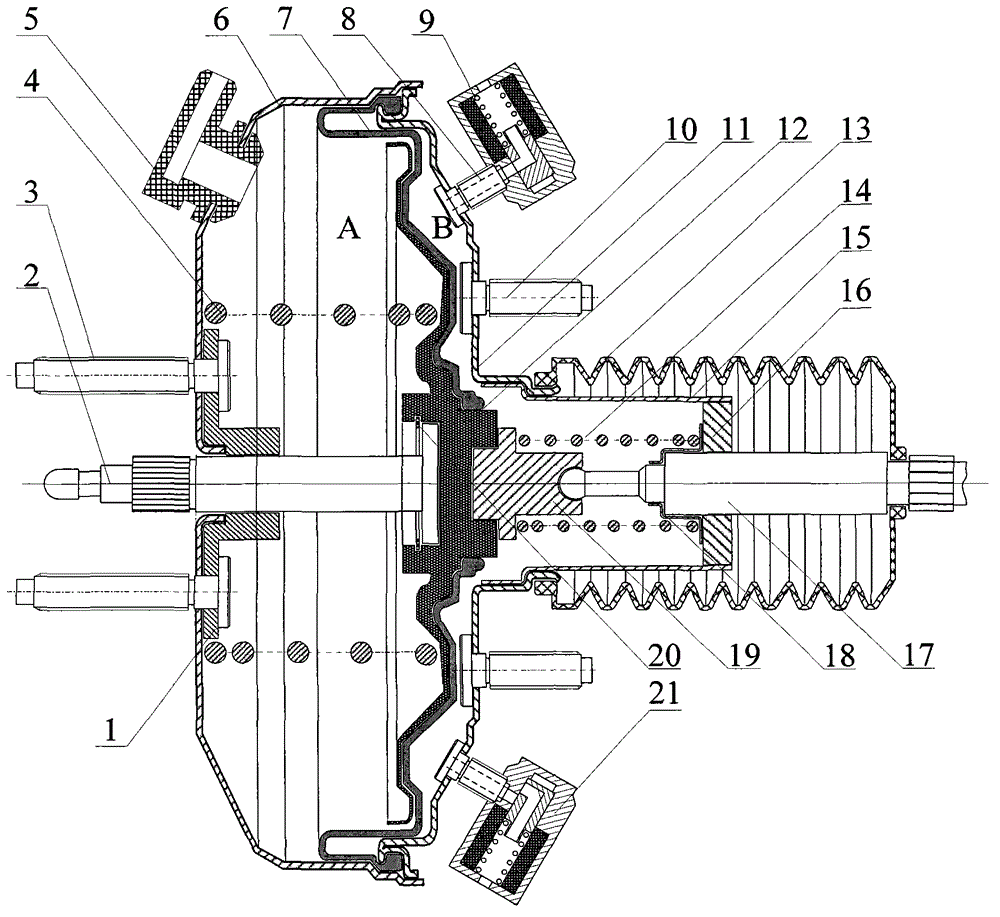
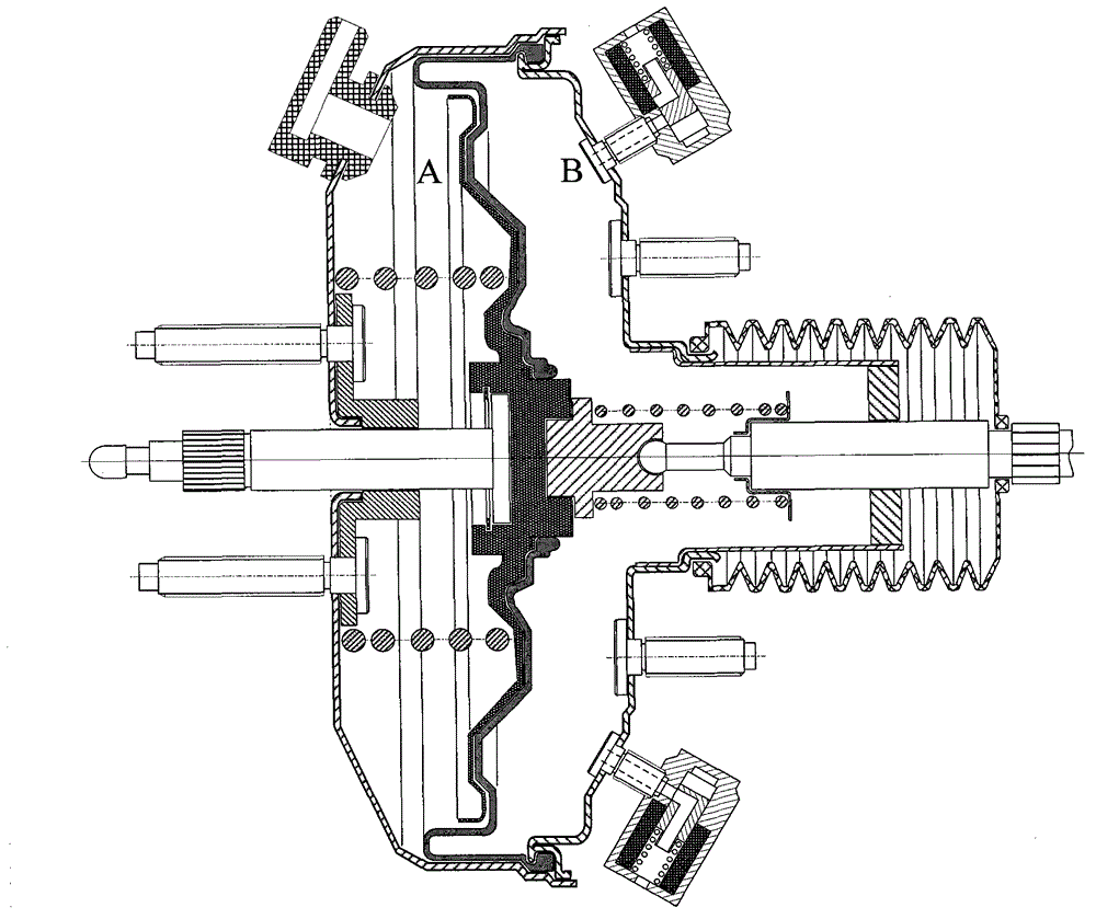
[0014] Such as figure 1 As shown, the electronically controlled vacuum booster of the present invention is composed of a front shell 6 and a rear shell 11 as a whole. The bracket 12 and the diaphragm 7 divide it into two front and rear cavities. The front cavity A is connected to The engine intake manifold is connected. The rear chamber B housing is equipped with a vacuum solenoid valve 9 and an air solenoid valve 21 on the outside through a hollow bolt 8. The vacuum solenoid valve 9 is connected to the engine intake manifold through a hose, and the air solenoid valve 21 is outside Open to the atmosphere, the front conductor 1 is arranged in the middle of the front shell 6, the supporting tube 15 is arranged in the middle of the rear shell 11, the rear conductor 16 is arranged at the rear end of the supporting tube 15, the booster push rod 2 is matched with the front conductor 1, and t...


PUM


Abstract

The invention provides an automobile-used electrical control vacuum booster which is divided into a front cavity and a rear cavity through a membrane, wherein a normally open vacuum solenoid valve and a normally closed air solenoid valve are arranged on a casing of the rear cavity. When a driver does not tread on a brake pedal, the front cavity is communicated with a suction manifold of an engine through a vacuum tube and the rear cavity is communicated with the suction manifold of the engine through the vacuum solenoid valve so as to keep pressures of the front cavity and the rear cavity balanced; in addition, the vacuum solenoid valve and the air solenoid valve are powered on under the control of a brake switch after the driver treads on the brake pedal, the vacuum solenoid valve is switched off to lead the rear cavity and the suction manifold of the engine not to be communicated, the air solenoid valve is switched on, external air is charged in the rear cavity to lead the pressure of the rear cavity to raise, the membrane is pushed to move forwards, and a brake assisting power is applied to a piston of a brake master cylinder through a push rod of a booster. When the electrical control vacuum booster is damaged, manual braking can be performed normally. The automobile-used electrical control vacuum booster simplifies the internal structure of a traditional vacuum booster, and can lower the manufacturing cost and the maintenance cost of the vacuum booster.

Description

technical field [0001] The invention relates to a vacuum booster used for boosting in an automobile braking system, in particular to an electronically controlled vacuum booster using a solenoid valve to control boosting. Background technique [0002] At present, the service brake system of a car usually adopts a servo brake system, which is formed by adding a set of power servo system on the basis of the human hydraulic brake system. The vacuum booster in the servo brake system is a device that provides braking boost. At present, the commonly used vacuum booster is surrounded by the front and rear housings, and the housing is divided into front and rear chambers by a diaphragm, and the air passage between the front and rear chambers is set on the bracket supporting the diaphragm. The airway is closed by the vacuum valve on the control valve when it is activated. An air valve is provided on the control valve. When the car brakes, the air valve is opened to provide air to th...

Claims


Application Information

Patent Timeline
IPC IPC(8): B60T13/56
Inventor 赵迎生
Owner ZHEJIANG NORMAL UNIVERSITY
Why Eureka
Try Eureka