Check patentability & draft patents in minutes with Patsnap Eureka AI!

riveted connection structure

A riveting and structuring technology, applied in the direction of connection, conductive connection, vehicle connector, etc., can solve the problems of easy fracture, reduced reliability, insufficient strength, etc., and achieve the effect of preventing fracture, improving mechanical strength, and preventing insufficient strength.

Active Publication Date: 2016-10-19
YAZAKI CORP
View PDF6 Cites 0 Cited by
  • Summary
  • Abstract
  • Description
  • Claims
  • Application Information

AI Technical Summary

Problems solved by technology

[0007] However, the tubular metal foil member made of metal foil has a problem that breakage occurs more easily than the tubular knitted member if it is caulked under the same conditions as the tubular knitted member.
In addition, the tubular metal foil member has the problem of being more likely to break than the tubular knitted member when a tensile force is applied.
Therefore, there are problems such as a decrease in reliability and insufficient strength related to electrical connections.

Method used


Image

  • riveted connection structure
  • riveted connection structure
  • riveted connection structure

Examples


Embodiment 1

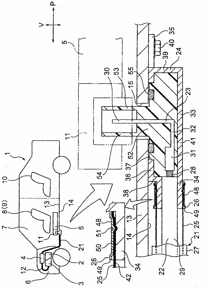
[0038] Next, Embodiment 1 will be described with reference to the drawings. figure 1 It is a schematic diagram of an automobile including the riveted connection structure of the present invention and an enlarged cross-sectional view of main parts. in addition, figure 2 is included figure 1 A perspective view of the terminal part of the riveted connection structure of the harness, image 3 It is a sectional view showing the structure of a cylindrical metal foil member.

[0039] The wire harness described later in this embodiment is intended to be a wire harness wired in a hybrid vehicle or an electric vehicle. Hereinafter, an example of a hybrid car will be given for description (in the case of an electric car, the structure, structure and effect of the wiring harness of the present invention are basically the same. In addition, it is not limited to a hybrid car or an electric car, and ordinary cars, etc. can also application of the present invention).

[0040] figure 1 In...

Embodiment 2

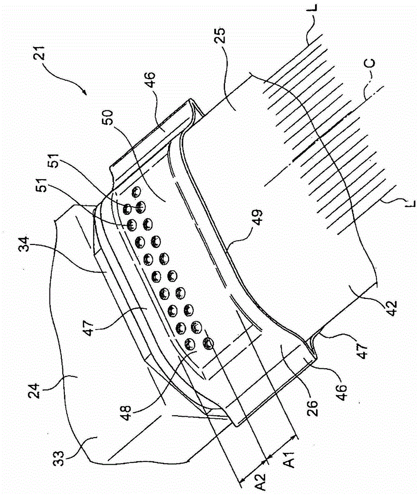
[0072] Next, Embodiment 2 will be described with reference to the drawings. Figure 4 It is a perspective view of the terminal part including the crimp connection structure which becomes another example of this invention. in addition, Figure 5 is included Figure 4 The model diagram of the car with the riveted connection structure and the enlarged cross-sectional view of the main part, Figure 6 It is a perspective view of a caulking connection structure as a comparative example. In addition, the same reference numerals are assigned to the same components as in the first embodiment described above, and detailed description thereof will be omitted.

[0073] exist Figure 4 as well as Figure 5 Among them, the caulking portion 61 formed by crushing the upper and lower portions 47 is formed by deforming the annular caulking member 26 inward in two stages. In addition, it is formed by deforming so as not to generate an edge like the peripheral edge portion 49 . That is, th...


PUM


Abstract

A swaging structure is provided, allowing to secure connection reliability or strength though a tubular metal foil member made of metal foil is included in its structure. The swaging, connection structure is the one that a ring-shaped swaging member is swaged so as to include an area of main contact with a plurality of points or plurality of lines and an area of main contact with area, and thereby to electrically and mechanically contact the tubular metal foil member and a tubular connection part. The swaging connection member is also made a connection structure arranged such that an edge of a circumferential edge part of the ring-shaped swaging member is arranged not to contact with the tubular metal foil member.

Description

technical field [0001] The present invention relates to a caulking connection structure in which a ring-shaped caulking member is caulked to electrically and mechanically connect a cylindrical metal foil member to a cylindrical connection portion. Background technique [0002] Patent Document 1 below discloses a technology related to a crimp connection structure in which an end portion of a cylindrical braided member arranged outside an electric wire and a cylindrical shield case are electrically connected by crimping an annular shield ring. In the above structure, the cylindrical braided member is formed into a cylindrical shape by braiding conductive ultra-thin wires. In addition, the shield shell is formed to have conductivity, and the end portion of the tubular braided member can be connected to the outer peripheral surface thereof. In addition, the shield ring is formed so that when crimping is performed with a caulking die with the cylindrical knitted member inserted ...

Claims


Application Information

Patent Timeline
Patent Type & Authority Patents(China)
IPC IPC(8): H01R13/655H01R4/18
CPCH01R4/182H01R4/20H01R4/206H01R13/65912H01R13/6593H01R2201/26
Inventor 远山荣一桥泽茂美
Owner YAZAKI CORP
Features
  • R&D
  • Intellectual Property
  • Life Sciences
  • Materials
  • Tech Scout
  • Unparalleled Data Quality
  • Higher Quality Content
  • 60% Fewer Hallucinations
Learn More