Chain conveying device

A technology of transmission device and chain, applied in the field of chain transmission device, can solve the problems of increasing site space, increasing manufacturing cost, increasing cost of occupied space, etc., and achieving the effect of reducing overall size and utilizing site utilization.

Inactive Publication Date: 2012-12-05
SUZHOU DONGLI MACHINERY
View PDF0 Cites 0 Cited by
  • Summary
  • Abstract
  • Description
  • Claims
  • Application Information

AI Technical Summary

Problems solved by technology

[0002] The transmission device used on the existing pallet welding machine generally pushes the workpiece to the processing point by the cylinder, and the cylinder is installed on the machine to push the movement of the workpiece, so that the machine needs to be enlarged and widened, and the installation of the cylinder takes up space, w

Method used


Image

  • Chain conveying device

Examples


Example Embodiment

[0010] The present invention will be described below with reference to the drawings.

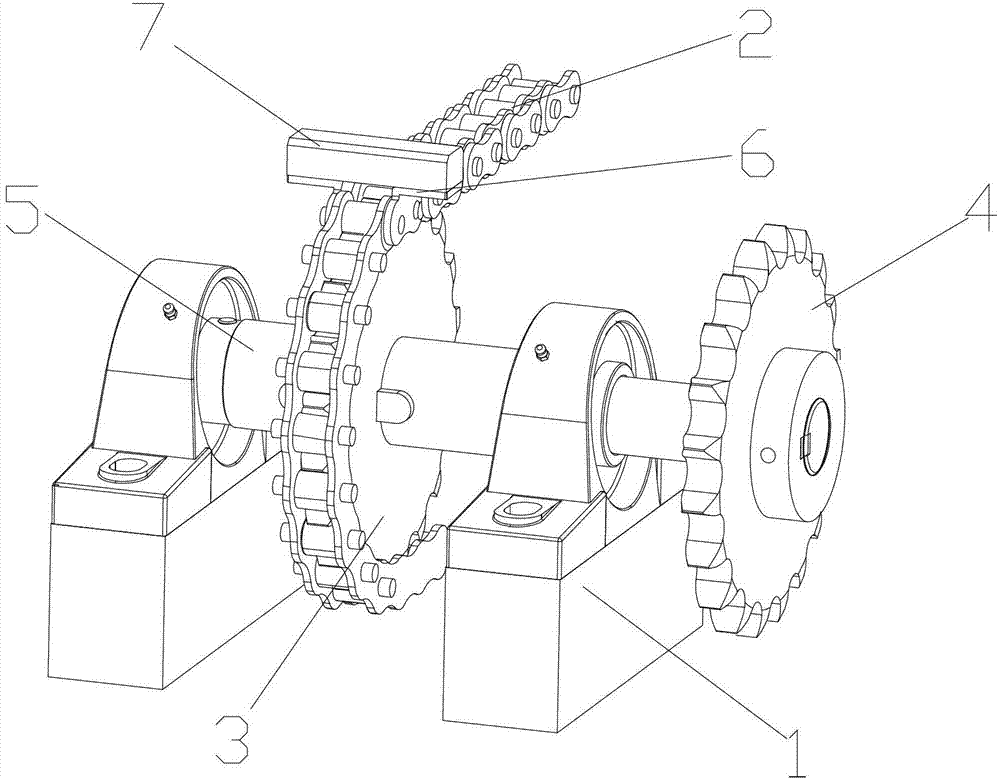
[0011] Attached figure 1 It is a chain transmission device according to the present invention, comprising a shaft frame 1, a chain 2; the shaft frame 1 is connected to a first gear 3 through a connecting shaft 5; the end of the connecting shaft 5 is provided with a second gear 4; The chain 2 is meshed with the first gear 3; the chain 2 of the chain is provided with a single-hole bent plate 6; the single-hole bent plate 6 is equipped with a baffle 7; the second gear 4 is connected to the motor to drive The connecting shaft 5 rotates, the movement of the first gear 3 drives the chain 2 to move, and the single-hole bent plate 6 on the chain 2 moves with the chain 2 to push the workpiece to move; the solution of the present invention is provided by the single-hole bent plate 6 and the baffle 7 on the chain 2 The movement of the workpiece is realized during the transmission process. When the first ...


PUM


Abstract

The invention discloses a chain conveying device. The device comprises a shaft bracket and a chain, wherein a first gear is connected to the shaft bracket through a connection shaft; a second gear is arranged at the tail end of the connection shaft; the chain is meshed with the first gear; a single-hole bending board is arranged at a sections of the chain; and a baffle is arranged on the single-hole bending board. According to the device, the single-hole bending board and the baffle are arranged on the chain, so that a workpiece can move in the conveying process; the baffle is driven to move after the first gear and the second gear rotate, and the baffle pushes the workpiece to a machining point, so that a conveying function of the device is realized; and the chain is arranged at the bottom of the device, so that a space is not increased, the residual space of the device is fully used, the finite space is fully and rationally used, the overall size of the device is reduced, and the site can be fully used.

Description

technical field [0001] The invention relates to a transmission device, in particular to a chain transmission device. Background technique [0002] The transmission device used on the existing pallet welding machine generally pushes the workpiece to the processing point by the cylinder, and the cylinder is installed on the machine to push the movement of the workpiece, so that the machine needs to be enlarged and widened, and the installation of the cylinder takes up space, which increases the manufacturing cost. Large size is not conducive to the economic benefits of production. At the same time, the placement of the machine increases the space of the site, and the occupied space increases the cost. Therefore, a transmission device that occupies a small space and can complete the processing well is needed. Contents of the invention [0003] In view of the above-mentioned technical problems, the object of the present invention is to propose a chain transmission device which...

Claims


Application Information

Patent Timeline
IPC IPC(8): B65G19/02B65G23/06
Inventor 叶晓峰
Owner SUZHOU DONGLI MACHINERY
Why Eureka
Try Eureka