Supercharge Your Innovation With Domain-Expert AI Agents!

Composite magnetic core and its manufacturing method

A composite and magnetic core technology, which is applied in the manufacture of inductors/transformers/magnets, the magnetism of inorganic materials, and electrical components, can solve problems such as difficult molds, sedimentation, and large specificity of magnetic powders, and avoid air bubbles and uneven magnetic properties. Effect

Inactive Publication Date: 2016-07-13
美桀电子科技(深圳)有限公司
View PDF8 Cites 1 Cited by
  • Summary
  • Abstract
  • Description
  • Claims
  • Application Information

AI Technical Summary

Problems solved by technology

[0005] However, it is easy to generate air bubbles in the colloid when filling the mold with the colloid mixed with magnetic powder, and it is difficult to make the mold a vacuum
In addition, the magnetic powder has a relatively large specific gravity relative to the colloid, and sedimentation will occur in the colloid, resulting in uneven magnetic distribution of the coated body.

Method used


Image

  • Composite magnetic core and its manufacturing method
  • Composite magnetic core and its manufacturing method
  • Composite magnetic core and its manufacturing method

Examples


no. 1 example

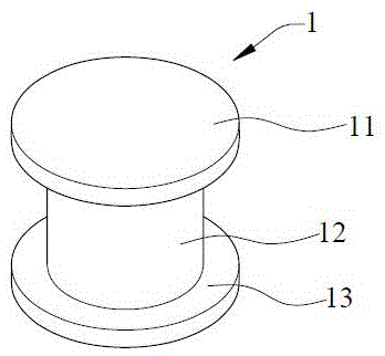
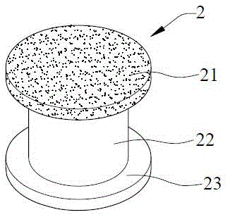
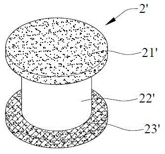
[0023] see Figure 2A . The magnetic core 2 includes an upper end portion 21, a columnar portion 22 and a lower end portion 23, wherein the upper end portion 21 and the lower end portion 23 are formed at both ends of the columnar portion 22, and the upper end portion 21 and the lower end portion 23 are perpendicular to the extending direction of the columnar portion 22. The cross-sectional area can be larger than the cross-sectional area of ​​the columnar portion 22 perpendicular to its extending direction, forming a magnetic core similar to the Chinese "工" or English "I".

[0024] At least one of the upper end portion 21 and the lower end portion 23 can be made of a mixture of powdered magnetic material and powdered adhesive in a predetermined ratio, and formed at both ends of the columnar portion 22 . Such as Figure 2A As shown, the upper end 21 of the magnetic core 2 is made of a mixture, and is bonded to one end of the columnar portion 22 by heating. Alternatively, the...

no. 2 example

[0036] see Figure 4The magnetic core 5 includes a core material 51 and a covering body 52 covering the core material 51 , the core material 51 is annular and has a hollow portion 510 , and the core material 51 has a notch 511 . The covering body 52 is made of a mixture of powdery magnetic material and powdery adhesive. The covering body 52 covers the core material 51 and forms a through hole 520 in the hollow portion 510 of the core material 51 . That is to say, the covering body 52 coaxially covers the entire core material 51 and forms a through hole 520 along the axis of the core material 51 .

[0037] Opening a notch 511 on the (ring) core material 51 can change the hysteresis curve of the core material 51, and using the (ring) core material 51 with the notch 511 to make an inductor can obtain better inductance characteristics, but the magnetic field lines will be at the notch 511 Exposure causes eddy current loss, increased reluctance and decreased magnetic permeability....


PUM


Abstract

The invention provides a composite magnetic core and a manufacturing method thereof. The method is as follows: firstly mix powdery magnetic material and powdery adhesive in a predetermined ratio to form a solid mixture, and then place a columnar core material in a columnar core of a mold. Hold the mold, and fill the mixture into the upper and lower ends of the mold to form a mold, or put the mixture, annular core material and mixture in another mold in sequence, and then heat the mold or the solid state in the other mold. mixture, so that the powdery magnetic material is bonded to each other by the powdery adhesive to be formed on both ends of the columnar core material, or the powdery magnetic material is coaxially coated on the whole of the annular core by the powdery adhesive to be bonded to each other and A through hole is formed along the axis of the annular core material. Therefore, a magnetic core with more than two kinds of materials can be produced through the application of the present invention.

Description

technical field [0001] The invention relates to a composite magnetic core and a manufacturing method thereof, in particular to a composite magnetic core applied to inductors, transformers or filters and a manufacturing method thereof. Background technique [0002] Magnetic cores can be used in inductors, filters or transformers etc. in various electronic devices. At present, there are roughly two methods of manufacturing magnetic cores: powder pressing process or magnetic colloid process. [0003] In terms of the powder pressing process, the powder material is pressed into a magnetic core by high temperature and high pressure, such as figure 1 Core 1 shown. Its production method is to firstly fill the magnetic powder into the mold, and then apply a large pressure to the mold to compress the magnetic powder. However, the cost of the process equipment that can provide huge pressure and the mold that can withstand huge pressure is very high. In addition, when the upper end p...

Claims


Application Information

Patent Timeline
Patent Type & Authority Patents(China)
IPC IPC(8): H01F27/255H01F1/22H01F41/02B22F3/00
Inventor 谭隆竞罗鹏程
Owner 美桀电子科技(深圳)有限公司
Features
  • R&D
  • Intellectual Property
  • Life Sciences
  • Materials
  • Tech Scout
  • Unparalleled Data Quality
  • Higher Quality Content
  • 60% Fewer Hallucinations
Learn More