Check patentability & draft patents in minutes with Patsnap Eureka AI!

Pneumatic split side measurer

A measuring instrument and pneumatic technology, applied in the field of measurement, can solve the problems such as the central axis not necessarily collinear, the measurement results are biased, and the same force cannot be guaranteed, so as to avoid errors, the measurement results are accurate, and it is conducive to repeated measurement.

Active Publication Date: 2015-01-21
KUNSHAN MINAMAX PRECISION IND
View PDF6 Cites 0 Cited by
  • Summary
  • Abstract
  • Description
  • Claims
  • Application Information

AI Technical Summary

Problems solved by technology

[0003] The first is the method of projection detection using the two-dimensional element, which mainly relies on the operator's visual reference. The disadvantage of this detection method is that the visual error of the tester, coupled with the slight deformation of the product, will cause the product to be detected incorrectly. The results will have a relatively high discrepancy with the actual data
[0004] The second method is to use a micrometer to measure the relevant parameters of the head of the product to be tested 30, and obtain it through conversion. The central axis of part 302 is not necessarily collinear, and the structure detected by this method will be quite different from the actual value of the product.
[0005] At present, a new measurement method is to measure by a specially designed profile measuring device. The whole process is based on the product, and there is no problem of product detection data error caused by the processing error of the inspection tool. With the inspection tool, even if there is a deviation in the diameter of the same batch of products, the deviation of the test result is relatively small, and the whole test process is the point-to-point contact between the product and the test tool, and there is no influence of the visual error of the tester on the test result. , but this profile measurer is divided into two steps of calibration and detection during measurement. Each step needs to compress the product. The existing compacting method is manually compacted. This pressing method There is no guarantee that the two pressing forces are the same, resulting in deviations in the final measurement results

Method used


Image

  • Pneumatic split side measurer
  • Pneumatic split side measurer
  • Pneumatic split side measurer

Examples


Embodiment Construction

[0026] The present invention will be further described below in conjunction with the accompanying drawings.

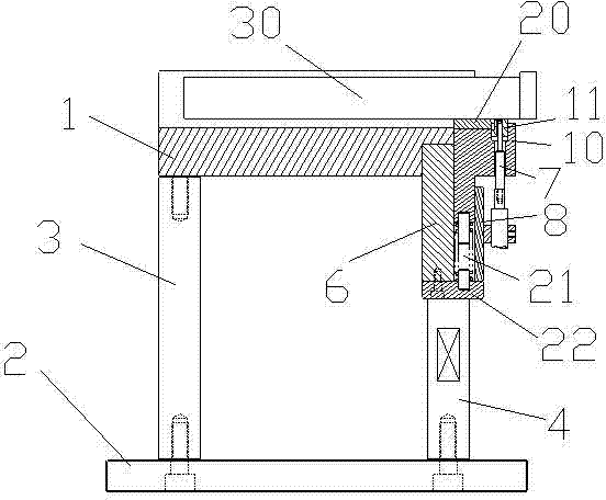
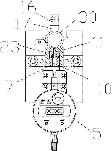
[0027] Such as Figure 1-Figure 8 As shown, a pneumatic profile measuring device includes a reference base 1 and a base plate 2, a rear support column 3 and a front support column 4 are connected between the reference base 1 and the base plate 2, and the middle position of the reference base 1 is set There is a V-shaped groove 101, the symmetry of the V-shaped groove 101 is 0.01, and the straightness is 0.01, which ensures that the axis of the product placed in the V-shaped groove 101 is on the same vertical plane as the center line of the V-shaped groove. A slider guide 6 is also connected between the reference seat 1 and the front support column 4, a slider 10 is arranged in the chute 601 of the slider guide 6, and a spring support plate is provided at the bottom of the slider guide 6 22. The chute 601 between the spring support plate 22 and the slider 10 is provide...


PUM


Abstract

The invention discloses a pneumatic split side measurer which comprises a reference base and a bottom plate, wherein a rear support column and a front support column are connected between the reference base and the bottom plate; a V-shaped groove is arranged at the middle part of the reference base; a digital display reading meter is fixed at an outer side of the reference base; a meter outfit probe is connected with the digital display reading meter; an axis of the meter outfit probe is in a same vertical plane with a central line of the V-shaped groove; a pressing rod is arranged above the central line of the V-shaped groove; and the pressing rod is driven by a thinned cylinder. With the adoption of the pneumatic split side measurer, a problem that in the prior art consistency of a pressing force of a manual split side measurer cannot be ensured is solved; the pressing force to a product during a measuring process is supplied by a cylinder, thereby ensuring that pressure for each pressing is same and a measurement result is more accurate and stable.

Description

technical field [0001] The invention relates to a pneumatic profile measuring device, which belongs to the technical field of measurement. Background technique [0002] The size detection of the straight cutting plane of the existing straight rod parts usually has the following two methods: [0003] The first is the method of projection detection using the two-dimensional element, which mainly relies on the operator's visual reference. The disadvantage of this detection method is that the visual error of the tester, coupled with the slight deformation of the product, will cause the product to be detected incorrectly. The results will have a relatively high variance with the actual data. [0004] The second method is to use a micrometer to measure the relevant parameters of the head of the product to be tested 30, and obtain it through conversion. The central axes of the portion 302 are not necessarily collinear, and there will be a large difference between the structure de...

Claims


Application Information

Patent Timeline
Patent Type & Authority Patents(China)
IPC IPC(8): G01B21/00G01B21/02
Inventor 李芳岳川魏吉仁
Owner KUNSHAN MINAMAX PRECISION IND
Features
  • R&D
  • Intellectual Property
  • Life Sciences
  • Materials
  • Tech Scout
  • Unparalleled Data Quality
  • Higher Quality Content
  • 60% Fewer Hallucinations
Learn More