Method for welding composite plates and explosive used by same

A welding method and composite sheet technology, which is applied to explosives, welding equipment, non-electric welding equipment, etc., can solve the problems of welding quality degradation, affecting the quality of double panels, repairing, etc., and achieve improved production efficiency, simple welding process, and combination of double panels good effect

Inactive Publication Date: 2013-01-09
北京中国科学院老专家技术中心
View PDF4 Cites 11 Cited by
  • Summary
  • Abstract
  • Description
  • Claims
  • Application Information

AI Technical Summary

Problems solved by technology

Therefore, when laying such explosives on a large plate, due to the deflection of the doubler plate, the laying thickness will be uneven, and the detonation velocity will change with the uneven thickness of the charge, which will seriously affect the welding quality of the explosive composite plate, and even local areas will appear. Welding quality is unqualified, need repair and manual repair welding phenomenon
Therefore, laying explosives is a manual operation process that requires careful and repeated inspections, and is inefficient, which seriously drags down the production efficiency of composite panels.
[0005] In addition, the detonation velocity of ammonium oil explosives (2.2-2.7km/sec) is much lower than the

Method used


Image

  • Method for welding composite plates and explosive used by same
  • Method for welding composite plates and explosive used by same
  • Method for welding composite plates and explosive used by same

Examples


Example Embodiment

[0044] Example one

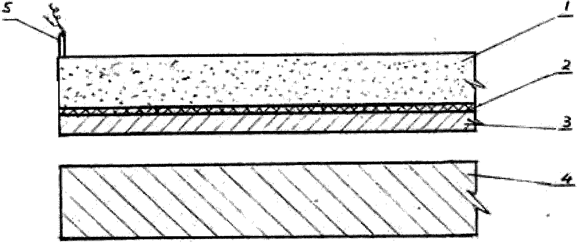
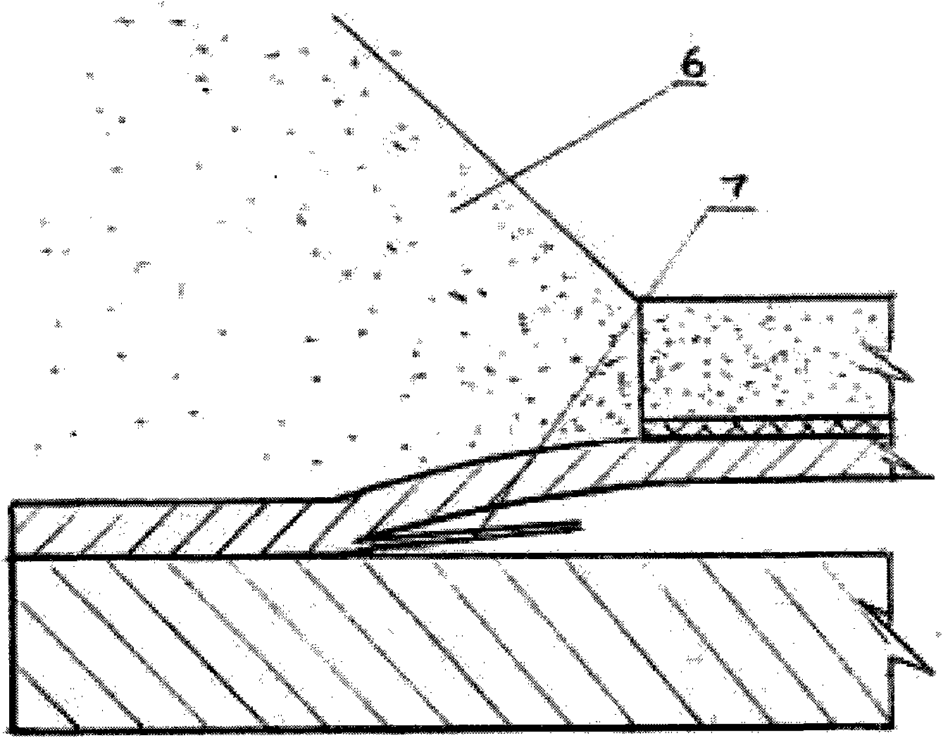
[0045] Figure 1a It is a schematic diagram of the explosive placement of the present invention; Figure 1b It is a schematic diagram of the instant of explosive explosion of the present invention;

[0046] Figure 2a It is a schematic diagram of a flat explosive provided in the first embodiment of the present invention;

[0047] image 3 It is the production flow chart of the emulsion explosive of the present invention.

[0048] The welding steps of the composite plate provided in this embodiment are as follows:

[0049] (1) Derusting the composite metal sheet first;

[0050] (2) Explosive welding in the field, the specific steps are:

[0051] 1. Place the substrate 4 (carbon steel) on a flat sandy surface, the thickness of the substrate 4 is 2cm;

[0052] 2. Place a number of pitch controllers made of metal foil on the substrate 4 (the number varies with the size and thickness of the composite board), so that the distance between the substrate 4 and the composite boa...

Example Embodiment

[0061] Example two

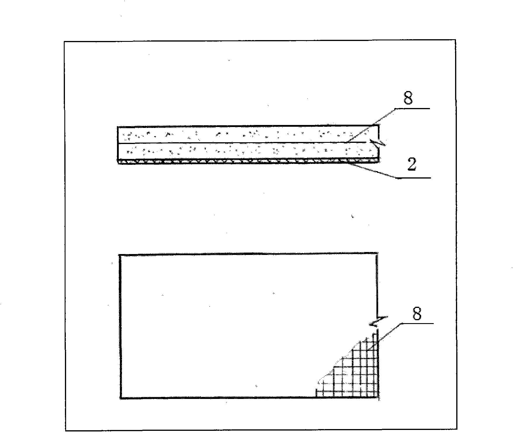
[0062] Using the same explosive welding steps as the first embodiment, the difference from the first embodiment is that the flat explosive used in this embodiment is such as Figure 2b As shown, a reinforcement layer 8 and a buffer layer 2 are respectively provided on both sides of the flat explosive.

[0063] Among them, the thickness of the flat explosive δ=3.0cm, and other parameters are the same as in the first embodiment, taking the base and the distance between the composite plates y=0.84cm, the collision angle of the composite plates α=13.04°, and the collision velocity of the composite plates υ p =681m / sec. The calculation shows that the strength of the joint surface of the obtained composite sheet is greater than the strength of the substrate material.


PUM

PropertyMeasurementUnit
Thicknessaaaaaaaaaa
Densityaaaaaaaaaa

Abstract

The invention discloses a method for welding composite plates and explosive used by the same. The method comprises the following steps of stacking more than two layers of metal plates into a plate group, distances are reserved among the plates, the flat explosive is paved on one side of the plate group and is detonated to enable the more than two layers of metal plates to be welded integrally. The method for welding the composite plates overcomes a plurality of defects including low production efficiency, unstable welding quality, high rejection rate and the like of existing composite plate welding technologies, and achieves the advantages of high production efficiency and good welding quality. The explosive is simple in structure, convenient to manufacture and convenient to store and transport.

Description

technical field [0001] The invention relates to a welding technology, in particular to a welding method of a composite plate and an explosive used therefor. Background technique [0002] Composite panels are widely used in special equipment such as chemical equipment, nuclear power plants, food processing equipment and semiconductor polysilicon production equipment. Research and practice have shown that although most metals and alloys have different structures and compositions, and even have huge differences in physical and chemical properties, it is possible to achieve reliable metallurgical bonding through explosive welding (composite) technology. With the further maturity of explosive welding technology, people can rationally combine metals or alloys according to needs, and obtain a large number of new materials with special properties in different varieties and specifications through explosive welding. Its component materials can be high strength and high toughness, or ...

Claims


Application Information

Patent Timeline
IPC IPC(8): B23K20/08C06B31/28
Inventor 邵丙璜
Owner 北京中国科学院老专家技术中心
Why Eureka
Try Eureka