Seat sliding rail mechanism
A slide rail and seat technology, which is applied in the direction of movable seats, etc., can solve the problems of high noise, low strength, heavy weight, etc., and achieve the effect of reducing noise frequency, reducing weight and manufacturing cost, and saving reinforcement sheets
- Summary
- Abstract
- Description
- Claims
- Application Information
AI Technical Summary
Problems solved by technology
Method used
Image

Examples
Embodiment 1
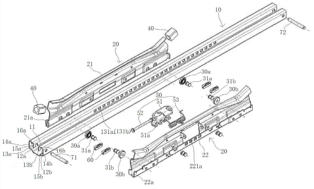
[0067] see Figure 6 , the seat slide mechanism shown in the figure includes a pair of lower slide rails 100 fixed on the vehicle floor and a pair of upper slide rail assemblies 200 hinged with the seat (Note Figure 6 Only one lower rail 100 and a set of upper slide rail assemblies 200 are shown in the assembly diagram, and the other lower rail 100 and a set of upper slide rail assemblies 200 have the same structure and assembly relationship).
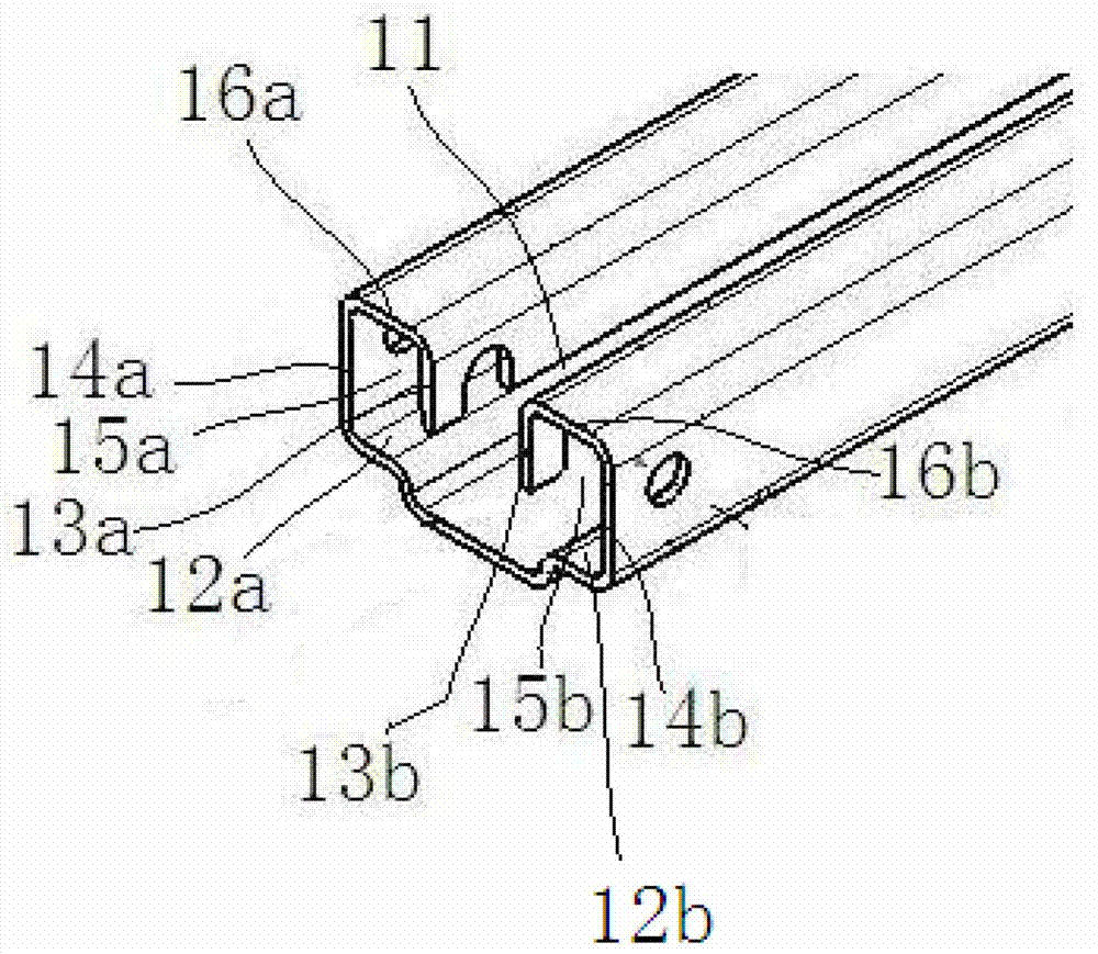
[0068] see Figure 7 , the cross-sectional shape of the lower rail 100 is a concave shape with the upper bottom removed, and the groove 110 in the middle of the lower rail 100 with the upper bottom groove removed constitutes a rolling groove for the upper rail assembly 200 to move back and forth. The two sides of the groove 110 The downward turning edges 131, 132 and the upward turning edges 141, 142 on both sides of the lower rail 100 respectively define the left and right lower turning edges 211, 221 in the upper slide rail assembl...
Embodiment 2
[0082] The difference between the seat slide rail mechanism of this embodiment and the seat slide rail mechanism of Embodiment 1 is that the vertical gap elimination mechanism 700 is slightly different, and the rest are the same as Embodiment 1.
[0083] see Figure 10 , the vertical clearance elimination mechanism 700 of this embodiment includes a small roller 711 , a swing piece 721 and a torsion spring 731 .
[0084] The swinging piece 721 is a roughly L-shaped swinging piece. The middle position of the swinging piece 721 has a fulcrum, and the fulcrum is hinged on the front side of the lower right flange 221 of the upper right slide rail plate 220 through a rivet 741. The swinging piece 721 Can swing around the rivet 741.
[0085] The small roller 711 is arranged on one end of the swing piece 721 through a rivet 751 shaft, and the other end of the swing piece 721 is connected to one end of the torsion spring 731, corresponding to the group of vertical clearance eliminatio...
Embodiment 3
[0089] The difference between the seat slide rail mechanism of this embodiment and the seat slide rail mechanism of Embodiment 1 is that the vertical gap elimination mechanism 700 is slightly different, and the rest are the same as Embodiment 1.
[0090] see Figure 11 In this embodiment, two groups of vertical gap elimination mechanisms 700 are respectively installed on the front and rear positions of the right lower flange 221 of the right upper slide rail plate 220 . The two groups of vertical clearance elimination mechanisms 700 share a torsion spring 732 .
[0091] Each set of vertical gap elimination mechanisms 700 also includes a small roller 712 and a swing piece 722 .
[0092] Each group of swinging pieces 722 is a roughly L-shaped swinging piece. The middle position of the swinging piece 722 has a fulcrum, and the fulcrum is hinged on the front and rear sides of the right lower flange 221 of the right upper slide rail plate 220 through a rivet 742. Sheet 722 can sw...
PUM
 Abstract
Description
Claims
Application Information
 - R&D
- Intellectual Property
- Life Sciences
- Materials
- Tech Scout
- Unparalleled Data Quality
- Higher Quality Content
- 60% Fewer Hallucinations
Browse by: Latest US Patents, China's latest patents, Technical Efficacy Thesaurus, Application Domain, Technology Topic, Popular Technical Reports.
© 2025 PatSnap. All rights reserved.Legal|Privacy policy|Modern Slavery Act Transparency Statement|Sitemap|About US| Contact US: help@patsnap.com