Check patentability & draft patents in minutes with Patsnap Eureka AI!

Pressure-resistant gear oil tank for compression machinery

A fuel tank, pressure-resistant technology, applied in mechanical equipment, liquid variable capacity machinery, machines/engines, etc., can solve the problems of poor heat dissipation capacity of the lower part, low overall strength, small oil storage capacity, etc., to enhance thermal conductivity, The effect of strengthening the heat dissipation area and reducing the thickness of the inner wall

Active Publication Date: 2013-03-27
南通荣恒环保设备有限公司
View PDF5 Cites 0 Cited by
  • Summary
  • Abstract
  • Description
  • Claims
  • Application Information

AI Technical Summary

Problems solved by technology

The above two designs are highly targeted, but there are also major defects: Design 1 has the disadvantage that the cooling ribs and reinforcing ribs increase the volume and external space of the fuel tank, but cannot increase the oil storage capacity of the fuel tank At the same time, there is a contradiction between the strong and thick ribs and the small surface area of ​​heat dissipation and heat dissipation. The mutual compromise in design eventually leads to low overall strength, weak heat dissipation capacity, small oil storage capacity, strong heat dissipation capacity in the upper part of the fuel tank, and strong heat dissipation capacity in the lower part. poor, resulting in a large temperature difference between the upper and lower parts of the fuel tank; Design 2, although avoiding the waste of fuel tank materials, increasing the strength and increasing the oil volume, but the surface of the special-shaped fuel tank is not smooth, it is difficult to place the fuel tank on the workbench during processing, increasing The processing cost of the fuel tank is reduced, and the heat dissipation capacity is poor, and the temperature difference of the upper part of the fuel tank with this structure is also large

Method used


Image

  • Pressure-resistant gear oil tank for compression machinery
  • Pressure-resistant gear oil tank for compression machinery
  • Pressure-resistant gear oil tank for compression machinery

Examples


Embodiment Construction

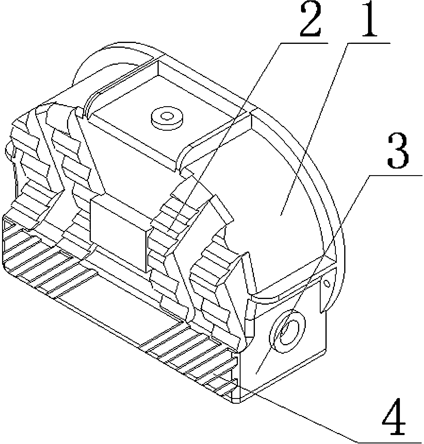
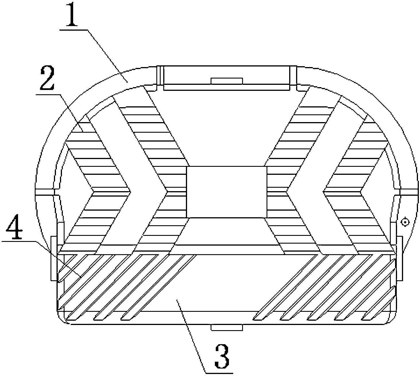
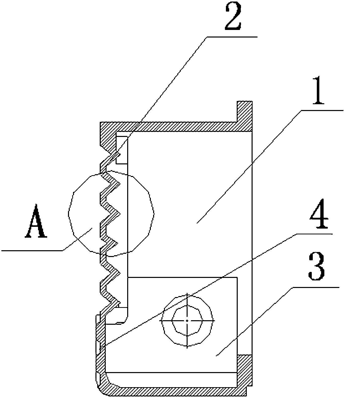
[0014] Such as Figure 1 to Figure 4 As shown, a pressure-resistant gear oil tank for compression machinery of the present invention includes an oil tank 1, the outer surface of the oil tank 1 is provided with a convex "X"-shaped reinforced heat pipe 2, and the bottom of the oil tank 1 is additionally provided with a heat-conducting The pipe 2 is of the same height as the oil storage chamber 3 , and the outer surface of the oil storage chamber 3 is provided with folds 4 . The heat pipe 2 and the oil storage chamber 3 protrude to the same height, and the surface of the oil tank 1 is still a plane, which is convenient for processing; the oil storage chamber 3 added at the bottom can effectively increase the oil storage capacity of the oil tank 1; the heat pipe 2 connects the oil tank 1. The surface is divided into several small surfaces, which has the strengthening effect of multiple complex folded edges. It has high strength and strong pressure, so the thickness of the inner wa...


PUM


Abstract

The invention discloses a pressure-resistant gear oil tank for compression machinery. The pressure-resistant gear oil tank for compression machinery comprises an oil tank. The pressure-resistant gear oil tank for compression machinery is characterized in that the outer surface of the oil tank is provided with an outward protruding heat conduction pipe; an oil storage cavity which has the height the same as that of the outward protruding heat conduction pipe is added on the bottom of the oil tank; and the outer surface of the oil storage cavity has folds. The pressure-resistant gear oil tank for compression machinery provided by the invention has the advantages that protruding heights of the heat conduction pipe and the oil storage cavity are equal, and the surface of the oil tank is still a plane, so that processing is convenient; the oil storage cavity added on the bottom can effectively increase the oil storage amount of the oil tank; the surface of the oil tank is separated into a plurality of small surfaces by the heat conduction pipe, so that the intensifying effect of a plurality complex folded edges can be achieved, intensity is high, and the born pressure is large, therefore, the inner wall thickness of the oil tank can be reduced, and consumed materials can be reduced effectively, and the heat conduction capability can be intensified effectively; and the folds on the oil storage cavity can enlarge heat radiation areas effectively and reduce the temperature difference of the upper part and the lower part of the oil tank, so that heat radiation is uniform.

Description

technical field [0001] The invention relates to an oil tank, in particular to a pressure-resistant gear oil tank for compression machinery. Background technique [0002] At present, the compression machinery in the market widely adopts the following two designs: 1. Ordinary flat oil tanks are added with cooling ribs to increase the strength and heat dissipation capacity at the same time; 2. Special-shaped convex oil tanks can realize the increase of oil storage At the same time, the hemming effect of the convex part has a more obvious strengthening effect on the overall strength. The above two designs are highly targeted, but there are also major defects: Design 1 has the disadvantage that the cooling ribs and reinforcing ribs increase the volume and external space of the fuel tank, but cannot increase the oil storage capacity of the fuel tank At the same time, there is a contradiction between the strong and thick ribs and the small surface area of ​​heat dissipation and he...

Claims


Application Information

Patent Timeline
Patent Type & Authority Applications(China)
IPC IPC(8): F04B39/02F04B39/06
Inventor 吴木兵曹旦刘康龚佳琦
Owner 南通荣恒环保设备有限公司
Features
  • R&D
  • Intellectual Property
  • Life Sciences
  • Materials
  • Tech Scout
  • Unparalleled Data Quality
  • Higher Quality Content
  • 60% Fewer Hallucinations
Learn More