Check patentability & draft patents in minutes with Patsnap Eureka AI!

Moving swing pipe clamping mechanism

A technology of clamping mechanism and collet, which is applied in the direction of drill pipe, casing, drilling equipment, etc., can solve the problems of time-consuming, labor-intensive, labor-intensive, etc., and achieve the effects of cost reduction, convenient and simple maintenance, and convenient alignment

Active Publication Date: 2015-03-18
JIANGSU WUXI MINERAL EXPLORATION MASCH GENERAL FAB CO LTD
View PDF9 Cites 0 Cited by
  • Summary
  • Abstract
  • Description
  • Claims
  • Application Information

AI Technical Summary

Problems solved by technology

[0004] When the drilling rig is equipped with air reverse circulation double-wall drill pipe or large-diameter drill pipe, the labor intensity of the driller's handling and loading and unloading of the drill pipe is relatively high, which is time-consuming and labor-intensive.

Method used


Image

  • Moving swing pipe clamping mechanism

Examples


Embodiment Construction

[0019] Below the present invention will be further described in conjunction with the embodiment in the accompanying drawing:

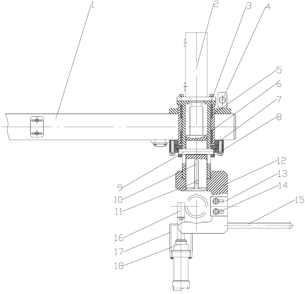
[0020] Such as figure 1 As shown, the present invention mainly includes a main arm 1 and a rotary sleeve 3 slidably installed on the main arm 1. The upper end of the rotary sleeve 3 is connected to the first oil cylinder 2 by bolts, and the lower end of the rotary sleeve 3 is connected to the collet 12 by external threads. A plug 6 is slidably installed in the swivel 3 , the upper end of the plug 6 is connected to the piston rod at the front end of the first oil cylinder 2 , the lower end of the plug 6 extends into the chuck 12 , and clamps the drill pipe together with the chuck 12 . The lower end of the main arm 1 is connected to the limit gland 7 by bolts, the limit cover 7 is embedded with a limit cover 8, and a limit pin 9 is installed in the limit cover 8, and the limit pin 9 passes through the rotary sleeve 3 and the plug 6. Connect the rotary s...


PUM


Abstract

The invention relates to a moving swing pipe clamping mechanism and belongs to the technical field of drilling machine equipment. The mechanism comprises a main arm and a teleflex installed on the main arm in a sliding mode, wherein the upper end of the teleflex is connected with a first hydro-cylinder through bolts, the lower end of the teleflex is connected with a chuck through outer screw threads, a top plug is installed in the teleflex in a sliding mode, the upper end of the top plug is connected with a piston rod which is located at the front end of the first hydro-cylinder and the lower end of the top plug penetrates into the chuck. The lower end of the main arm is connected with a limit gland through the bolts, a limit cover is nested into the limit gland, a spacer pin is installed inside the limit cover, the spacer pin penetrates through the teleflex and the top plug, and the teleflex and the top plug are connected into an integrated structure. The lower end of the chuck is connected with a hydro-cylinder support, and the hydro-cylinder support is connected with a second hydro-cylinder through the bolts. The mechanism is simple, compact and reasonable in structure, the hydraulic energy of the drilling machine is used as a driving force and lowers the cost, the chucking is safe and reliable when the drill pipe is lifted and the alignment is convenient after reaching the position, and the mechanism is convenient to maintain and simple in maintenance and flexible and reliable in movement due to little restriction between parts.

Description

technical field [0001] The invention relates to a clamping mechanism for a swing pipe, which belongs to the technical field of drilling rig equipment. Background technique [0002] A drilling rig is a mechanical device that drives a drilling tool to drill underground to obtain physical geological data in geological exploration. Also known as drilling machine. The main function is to drive the drilling tool to break the rock at the bottom of the hole, and to lower or lift the drilling tool in the hole. It can be used to drill cores, ore cores, cuttings, gaseous samples, liquid samples, etc., to ascertain the conditions of underground geology and mineral resources. [0003] The general name of the entire drilling pipe string and its joints used in the drilling construction is called the drilling tool (. The drilling tool is composed of a driving drill pipe, a drill pipe, a core pipe, and a reamer and a drill bit at the bottom. A sedimentation pipe or drill collar is added t...

Claims


Application Information

Patent Timeline
Patent Type & Authority Patents(China)
IPC IPC(8): E21B19/18
Inventor 朱利根
Owner JIANGSU WUXI MINERAL EXPLORATION MASCH GENERAL FAB CO LTD
Features
  • R&D
  • Intellectual Property
  • Life Sciences
  • Materials
  • Tech Scout
  • Unparalleled Data Quality
  • Higher Quality Content
  • 60% Fewer Hallucinations
Learn More