Check patentability & draft patents in minutes with Patsnap Eureka AI!

Power source circuit shutoff apparatus

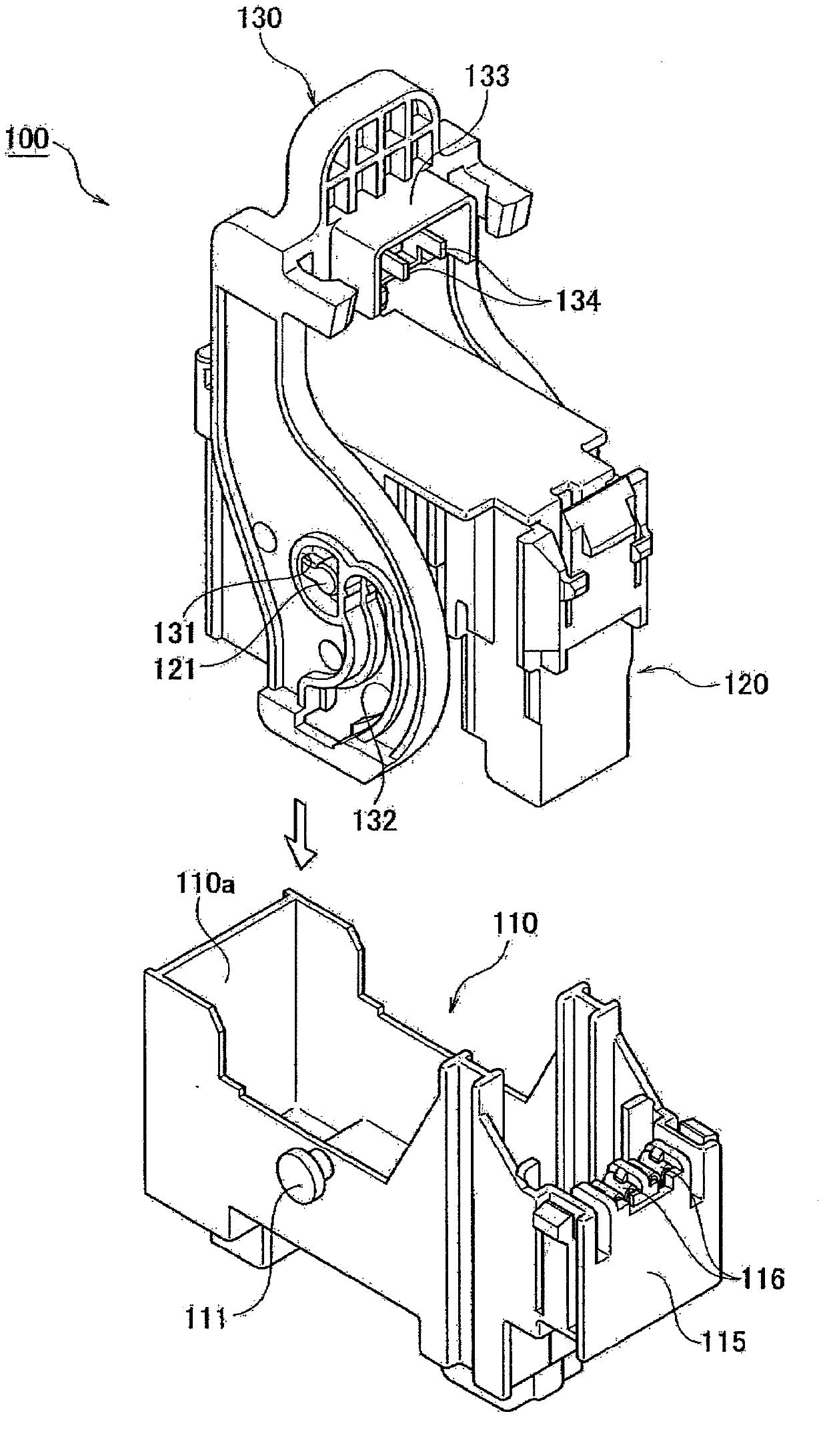
A technology for cutting off devices and power circuits, applied to parts of circuits, coupling devices, and connecting devices, etc., which can solve the problems of decreased operability of the control lever 130 and increased force of the control lever 130 rotation, etc.

Active Publication Date: 2013-06-05
YAZAKI CORP
View PDF6 Cites 4 Cited by
  • Summary
  • Abstract
  • Description
  • Claims
  • Application Information

AI Technical Summary

Problems solved by technology

Therefore, when the pair of second signal terminals 134 is in contact with the pair of first signal terminals 116, the force for rotating the lever 130 increases, and thus the operability of the lever 130 may be reduced.

Method used


Image

  • Power source circuit shutoff apparatus
  • Power source circuit shutoff apparatus
  • Power source circuit shutoff apparatus

Examples


Embodiment Construction

[0043] Hereinafter, a power circuit shutoff device according to an embodiment of the present invention will be described with reference to the drawings. Specifically, the following contents are explained: (1) Structure of power circuit cut-off device; (2) Structure of signal terminal; (3) Structure of main terminal; (4) Structure of power circuit; (5) Function and effect ; (6) Variations; (7) Other implementations.

[0044] In addition, in the following description of drawings, the same or similar code|symbol is attached|subjected to the same or similar part. However, the drawings are merely schematic illustrations, and ratios of dimensions and the like are different from actual ones.

[0045] Therefore, specific dimensions and the like should be determined in consideration of the following description. In addition, there are also parts in which mutual dimensional relationships and ratios are different among the drawings.

[0046] (1) Structure of the power circuit cut-off ...


PUM


Abstract

The present invention realtes to a power source circuit shutoff apparatus. In the power source circuit shutoff apparatus, with the lever rotated from a connector mating start position to a connector mating completion position, a pair of first signal terminals and a pair of second signal terminals are brought into on-state after a pair of first main terminals and a pair of second main terminals are brought into on-state. With the lever rotated from the connector mating completion position to the connector mating start position, a pair of first main terminals and a pair of second main terminal are brought into off-state after a pair of first signal terminals and a pair of second signal terminals are brought into off-state. The pair of first signal terminals and the pair of second signal terminals are each disposed along a straight line extending in a direction perpendicular to a rotational spindle direction of the lever.

Description

technical field [0001] The present invention relates to a power circuit disconnecting device which realizes connection and disconnection of a power circuit by fitting and disengaging a connector housing with a lever. Background technique [0002] Conventionally, in electric vehicles (EV) and hybrid electric vehicles (HEV), in order to ensure the safety of work such as maintenance of the electrical system, a power circuit disconnection device (power plug: service plug) (for example, refer to Patent Document 1 (Japanese Patent Laid-Open No. 2002-298704)). [0003] As a power circuit cut-off device, the applicant proposes Figure 1 ~ Figure 4 device shown. Specifically, as Figure 1 ~ Figure 3 As shown, the power circuit disconnecting device 100 includes: a first connector housing 110; a second connector housing 120 that fits and disengages from the first connector housing 110; and is disposed on the second connector housing 120, The lever 130 is rotatable, and a fitting for...

Claims


Application Information

Patent Timeline
IPC IPC(8): H01H27/00H01H21/22
CPCH01R13/62955H01H21/22H01H27/00H01H35/003H01R13/62938H01R31/08H01R2201/26H01R13/701
Inventor 逸见文俊
Owner YAZAKI CORP
Features
  • R&D
  • Intellectual Property
  • Life Sciences
  • Materials
  • Tech Scout
  • Unparalleled Data Quality
  • Higher Quality Content
  • 60% Fewer Hallucinations
Learn More