Supercharge Your Innovation With Domain-Expert AI Agents!

Common Mode Rejection Circuit

A technology of common-mode suppression and common-mode current, applied in electrical components, differential amplifiers, power oscillators, etc., can solve problems such as increasing oscillator loss, increasing power consumption, and reducing oscillator quality factor

Active Publication Date: 2016-12-28
APPLE INC
View PDF4 Cites 0 Cited by
  • Summary
  • Abstract
  • Description
  • Claims
  • Application Information

AI Technical Summary

Problems solved by technology

Common mode currents at the second harmonic frequency do not contribute to stored energy, but contribute to dissipated energy
Therefore, common-mode currents reduce the quality factor of the oscillator and thus may increase losses in oscillators with no common-mode rejection circuitry or with limited common-mode rejection circuitry
Finally, this may result in increased power consumption for a given phase noise performance

Method used


Image

  • Common Mode Rejection Circuit
  • Common Mode Rejection Circuit
  • Common Mode Rejection Circuit

Examples


Embodiment Construction

[0016] Different embodiments of the invention will be discussed subsequently with reference to the figures. In advance, the same reference numerals are given to objects having the same or similar functions, so that objects referred to by the same reference numerals in different embodiments are interchangeable and their descriptions are mutually applicable.

[0017] Embodiments of the present invention are discussed below, after discussing common designs of common-mode rejection circuit elements optimized for high frequency and low voltage headroom.

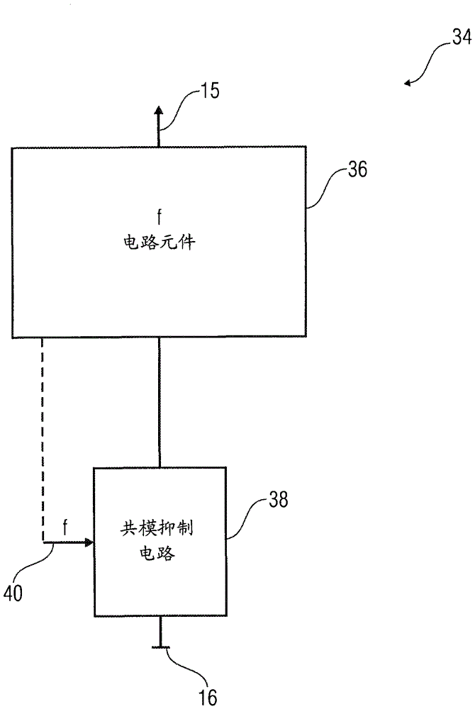
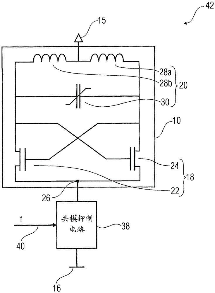
[0018] image 3 An oscillating device 11 is shown comprising an oscillator 10 and a common mode rejection circuit element 12 . The oscillator 10 and the common mode rejection circuit element 12 are connected in series. Thus, the oscillator is connected directly to the power supply 15 and to ground 16 via the common mode rejection circuit element 12 . The common mode suppression circuit element 12 includes a resonant circuit inc...


PUM


Abstract

The invention discloses a common mode suppression circuit. A circuit includes a circuit element and a common mode rejection circuit element. The circuit element is configured to operate at a selected frequency within a variable frequency range, and the common-mode rejection circuit element is configured to suppress common-mode current through the circuit element, wherein the common-mode rejection circuit element is adjustable.

Description

technical field [0001] Embodiments of the invention relate to a circuit comprising a common mode rejection circuit, a method for operating the circuit, an oscillating device comprising the common mode rejection circuit, and a method for operating the oscillating device. Background technique [0002] A common mode rejection circuit may be used for the purpose of suppressing common mode and generated common mode currents through a circuit, such as through the circuit of a radio frequency transceiver of a mobile communication device or through an oscillator. Such common modes are disturbances caused by oscillators or by circuits operating at one frequency. For example, oscillators that include differential amplifiers driven with high signal swings suffer from large signal effects (eg, common mode). Common mode appears on the oscillator's signal output as well as on ground and power supplies. This common-mode signal or main oscillator signal can lead to the generation of volta...

Claims


Application Information

Patent Timeline
Patent Type & Authority Patents(China)
IPC IPC(8): H03F3/45
CPCH03B5/1215H03B5/1228H03B5/124H03B5/1265H03B5/1268H03B5/1284H03B2200/0054H03B2201/035H03B2202/05
Inventor A·罗伊特迈尔
Owner APPLE INC
Features
  • R&D
  • Intellectual Property
  • Life Sciences
  • Materials
  • Tech Scout
  • Unparalleled Data Quality
  • Higher Quality Content
  • 60% Fewer Hallucinations
Learn More