Smart Wireless Charging Vacuum Cleaner System
A wireless charging and vacuum cleaner technology, applied in the field of energy transmission, can solve the problems of exposed charging contacts of smart vacuum cleaners, inability to accurately dock and charge, etc., and achieve the effect of enhancing safety
- Summary
- Abstract
- Description
- Claims
- Application Information
AI Technical Summary
Problems solved by technology
Method used
Image


Examples
specific Embodiment approach 1
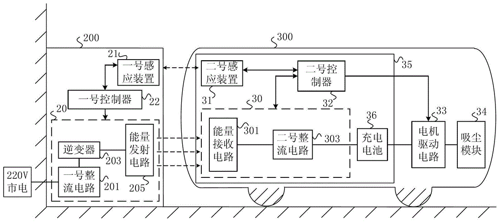
[0028] Specific implementation mode one, combining figure 1 This specific embodiment will be described. figure 1 It is a structural block diagram illustrating a specific implementation of an intelligent wireless charging vacuum cleaner system. In this embodiment, the intelligent wireless charging vacuum cleaner system includes a charging stand 200 and a vacuum cleaner body 300 . The charging stand 200 is connected to 220V mains, and the charging stand 200 can charge the vacuum cleaner body 300 wirelessly. The vacuum cleaner body 300 is used for automatically cleaning the dust and garbage on the ground.
[0029] The charging stand 200 includes an energy transmitting module 20 , a No. 1 sensing device 21 and a No. 1 controller 22 .
[0030] The energy transmitting module 20 is connected to the 220V commercial power through a power line, and is used for converting the 220V commercial power and outputting an alternating magnetic field.
[0031] When the vacuum cleaner body 300...
specific Embodiment approach 2
[0038] Specific embodiment two, combine figure 1 This specific embodiment will be described. The difference between this specific embodiment and the intelligent wireless charging vacuum cleaner system described in the first specific embodiment is that the energy transmission module 20 includes a No. 1 rectifier circuit 201 , an inverter 203 and an energy transmission circuit 205 .
[0039] The electrical signal input terminal of the No. 1 rectifier circuit 201 is connected to the 220V mains through the power line, so as to rectify the 220V mains into direct current.
[0040] The electrical signal input terminal of the inverter 203 is connected to the electrical signal output terminal of the No. 1 rectifier circuit 201 for inverting the DC power output by the No. 1 rectifier circuit 201 into AC power.
[0041]The electrical signal input end of the energy transmitting circuit 205 is connected with the electrical signal output end of the inverter 203 for converting the alternati...
specific Embodiment approach 3
[0042] Specific embodiment three, combine figure 1 This specific embodiment will be described. The difference between this specific embodiment and the intelligent wireless charging vacuum cleaner system described in the first and second specific embodiments is that the energy receiving module 30 includes an energy receiving circuit 301 and a No. 2 rectifying circuit 303 .
[0043] The energy receiving circuit 301 is used for receiving the alternating magnetic field generated by the energy transmitting circuit 205 and converting the alternating magnetic field into alternating current.
[0044] The electrical signal input terminal of the No. 2 rectifier circuit 303 is connected with the electrical signal output terminal of the energy receiving circuit 301 for converting the alternating current generated by the energy transmitting circuit 301 into direct current and providing the direct current to the rechargeable battery 36 .
PUM
 Abstract
Description
Claims
Application Information
 - R&D
- Intellectual Property
- Life Sciences
- Materials
- Tech Scout
- Unparalleled Data Quality
- Higher Quality Content
- 60% Fewer Hallucinations
Browse by: Latest US Patents, China's latest patents, Technical Efficacy Thesaurus, Application Domain, Technology Topic, Popular Technical Reports.
© 2025 PatSnap. All rights reserved.Legal|Privacy policy|Modern Slavery Act Transparency Statement|Sitemap|About US| Contact US: help@patsnap.com