Supercharge Your Innovation With Domain-Expert AI Agents!

Method and apparatus for determining the state of an electrically controlled valve

An electric device and electric control technology, applied to measuring devices, frequency measuring devices, circuits, etc., can solve the problem of not knowing the interference

Active Publication Date: 2016-03-09
DANFOSS POWER SOLUTIONS GMBH & CO
View PDF3 Cites 0 Cited by
  • Summary
  • Abstract
  • Description
  • Claims
  • Application Information

AI Technical Summary

Problems solved by technology

Disturbances, for example in the form of valves that are no longer fully open or closed, are practically not known with the proposed method
Furthermore, the method described there is likewise only suitable for quasi-stationary systems

Method used


Image

  • Method and apparatus for determining the state of an electrically controlled valve
  • Method and apparatus for determining the state of an electrically controlled valve
  • Method and apparatus for determining the state of an electrically controlled valve

Examples


Embodiment Construction

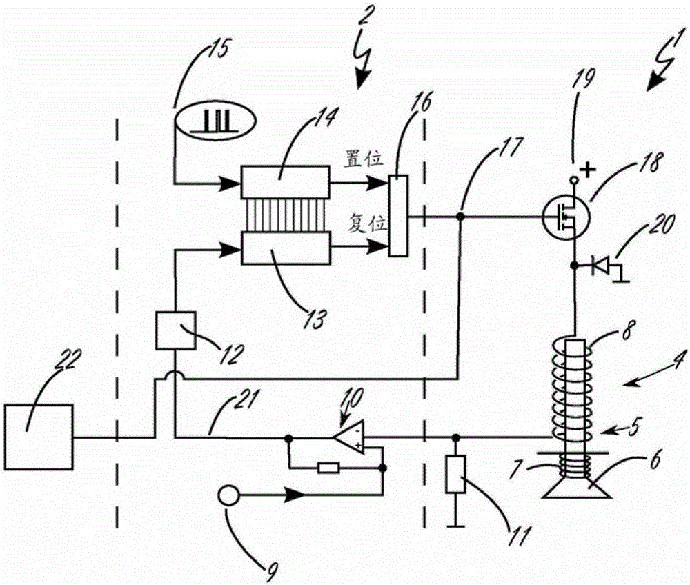
[0034] figure 1 A first possible circuit arrangement 1 of the control unit 2 for controlling the valve unit 4 is shown in a schematic wiring diagram. In the exemplary embodiment shown, the valve unit 4 has an actuator 5 (in the exemplary embodiment substantially formed by an electrical coil 8 ) with a valve body 6 . In the exemplary embodiment shown here, the actuator 5 brings about an upward movement of the valve body 6 when current is introduced into the electric coil 8 (so that, for example, the valve head comes into contact with the valve seat and accordingly closes the valve unit 4 ). Conversely, the return spring 7 provided in the exemplary embodiment brings about a reverse movement of the valve body 6 if the electric coil 8 is not passed through by current. Of course, the valve body 6 can also be opened again by an external force (for example by a pressure difference across the valve head) or the like.

[0035] The actual switching on or off of the actuator 5 (and thu...


PUM


Abstract

The invention relates to a method (3) for determining (33) a state characteristic value (28) of an electrical device (4) controlled with a time-varying control signal (17). At least one state characteristic value ( 28 ) is determined using the frequency of the time-varying control signal ( 17 ) and / or the switching ratio of the time-varying control signal ( 17 ).

Description

technical field [0001] The invention relates to a method for determining at least one state characteristic value of an electrical device which is at least temporarily and / or at least partially controlled by means of a time-varying control signal. The invention also relates to an electrical control device for at least temporarily and / or at least partially determining at least one state characteristic value of an electrical device controlled with a time-varying control signal. Background technique [0002] Currently, the most different kinds of electrical devices are controlled using electric current. [0003] If the electrical device is in different states, for example as a function of determined measured values ​​and / or at different points in time, the control of the electrical device can take place using a time-varying control signal. The electrical device is then generally in a certain state depending on the type of control signal applied. It is possible here that a cert...

Claims


Application Information

Patent Timeline
Patent Type & Authority Patents(China)
IPC IPC(8): G01R31/327H01H47/32G01R31/72
CPCG01R31/3275G01R31/3278H01H47/325G01R31/72G01R31/327G01R23/02G01R31/00
Inventor S.芬克M.萨特巴克
Owner DANFOSS POWER SOLUTIONS GMBH & CO
Features
  • R&D
  • Intellectual Property
  • Life Sciences
  • Materials
  • Tech Scout
  • Unparalleled Data Quality
  • Higher Quality Content
  • 60% Fewer Hallucinations
Learn More