Optical lens system for image taking
An imaging lens and lens technology, applied in the field of imaging lens groups, can solve the problems of difficult control of imaging quality around the image, unfavorable Petzval sum, etc., and achieve the effect of shortening the total optical length, correcting aberrations, and maintaining miniaturization.
- Summary
- Abstract
- Description
- Claims
- Application Information
AI Technical Summary
Problems solved by technology
Method used
Image
Examples
no. 1 example
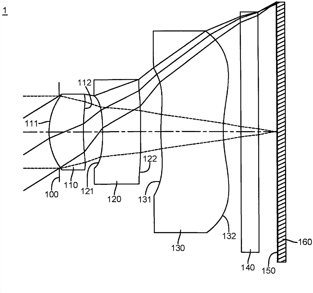
[0096] Please refer to Figure 1A Shown is a schematic structural diagram of the first embodiment of the imaging lens group. The imaging lens group 1 is from the object side to the image side (that is, along the Figure 1A from the left side to the right side) sequentially includes an aperture 100, a first lens 110, a second lens 120, a third lens 130, an infrared infrared filter 140 and an image set on an imaging surface 150 sensing element 160 .
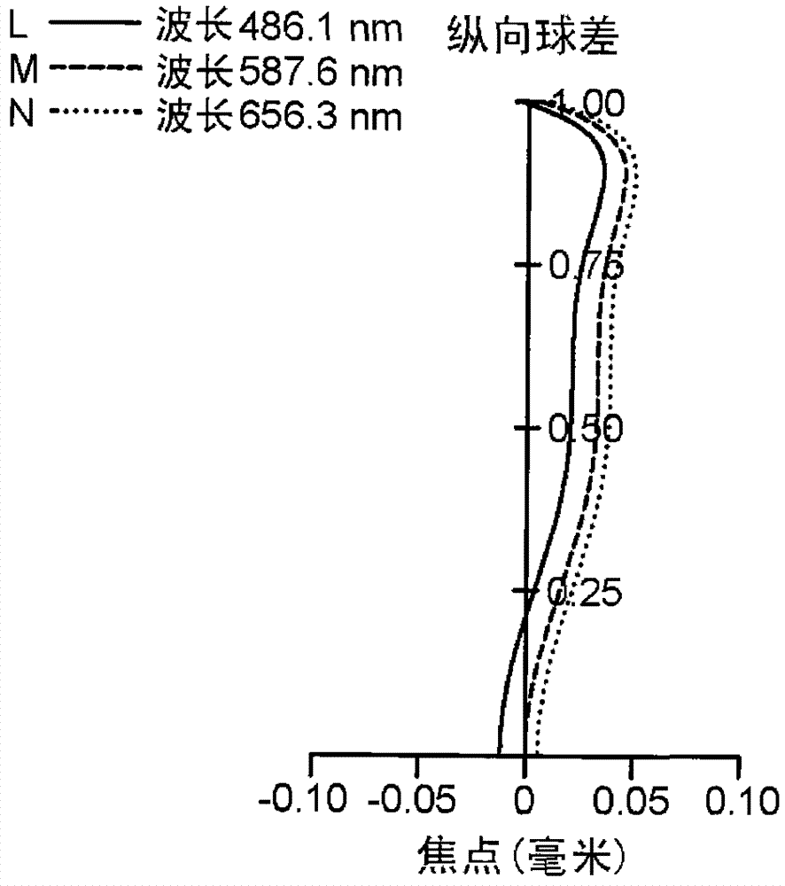
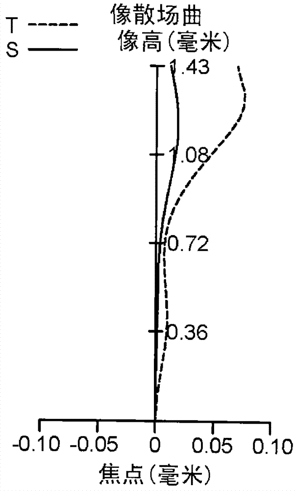
[0097] In this embodiment, the first lens 110 is made of plastic material and has positive refractive power. The object side 111 of the first lens is an aspherical convex surface, and the image side 112 of the first lens is an aspherical concave surface. The second lens 120 is made of plastic material and has a negative refractive power. The second lens object side 121 and the second lens image side 122 are both aspherical concave surfaces. The third lens 130 is made of plastic material and has negative refractive power. The objec...
no. 2 example
[0112] Please refer to Figure 2A As shown, it is a schematic structural diagram of the second embodiment of the imaging lens group disclosed in the present invention. Its specific implementation is substantially the same as the aforementioned first embodiment, which means that it has the same function or structure. To simplify the description, only the differences will be described below, and the rest of the similarities will not be repeated.
[0113] In this embodiment, the first lens 210 is made of plastic material and has positive refractive power, and the object side 211 and the image side 212 of the first lens are both aspherical convex surfaces. The second lens 220 is made of plastic material and has a negative refractive power. The second lens object side 221 and the second lens image side 222 are both aspherical concave surfaces. The third lens 230 is made of plastic and has negative refractive power. The object side 231 of the third lens is an aspheric convex surfac...
no. 3 example
[0126] Please refer to Figure 3A As shown, it is a schematic structural diagram of the third embodiment of the imaging lens group disclosed in the present invention. Its specific implementation is substantially the same as the aforementioned first embodiment, which means that it has the same function or structure. To simplify the description, only the differences will be described below, and the rest of the similarities will not be repeated.
[0127] In this embodiment, the first lens 310 is made of plastic material and has positive refractive power, and the object side 311 and the image side 312 of the first lens are both aspherical convex surfaces. The second lens 320 is made of plastic material and has negative refractive power. Both the object side 321 and the second image side 322 of the second lens are aspherical concave surfaces. The third lens 330 is made of plastic material and has negative refractive power. The object side 331 of the third lens is an aspherical con...
PUM
 Abstract
Description
Claims
Application Information
 - R&D
- Intellectual Property
- Life Sciences
- Materials
- Tech Scout
- Unparalleled Data Quality
- Higher Quality Content
- 60% Fewer Hallucinations
Browse by: Latest US Patents, China's latest patents, Technical Efficacy Thesaurus, Application Domain, Technology Topic, Popular Technical Reports.
© 2025 PatSnap. All rights reserved.Legal|Privacy policy|Modern Slavery Act Transparency Statement|Sitemap|About US| Contact US: help@patsnap.com


