Check patentability & draft patents in minutes with Patsnap Eureka AI!

Rotary electric machine rotor

A technology of rotary electric machine and rotor, applied in the field of rotor, can solve the problem of high magnetic permeability of electromagnetic steel plate

Inactive Publication Date: 2013-07-10
NISSAN MOTOR CO LTD +1
View PDF3 Cites 10 Cited by
  • Summary
  • Abstract
  • Description
  • Claims
  • Application Information

AI Technical Summary

Problems solved by technology

However, magnetic steel sheets such as those used in rotors have large magnetic permeability

Method used


Image

  • Rotary electric machine rotor
  • Rotary electric machine rotor
  • Rotary electric machine rotor

Examples


Embodiment Construction

[0024] Selected embodiments will now be explained with reference to the drawings. It will be apparent to those skilled in the art from this disclosure that the following description of the embodiments is provided for illustration only and not for the purpose of limiting the invention as defined by the appended claims and their equivalents.

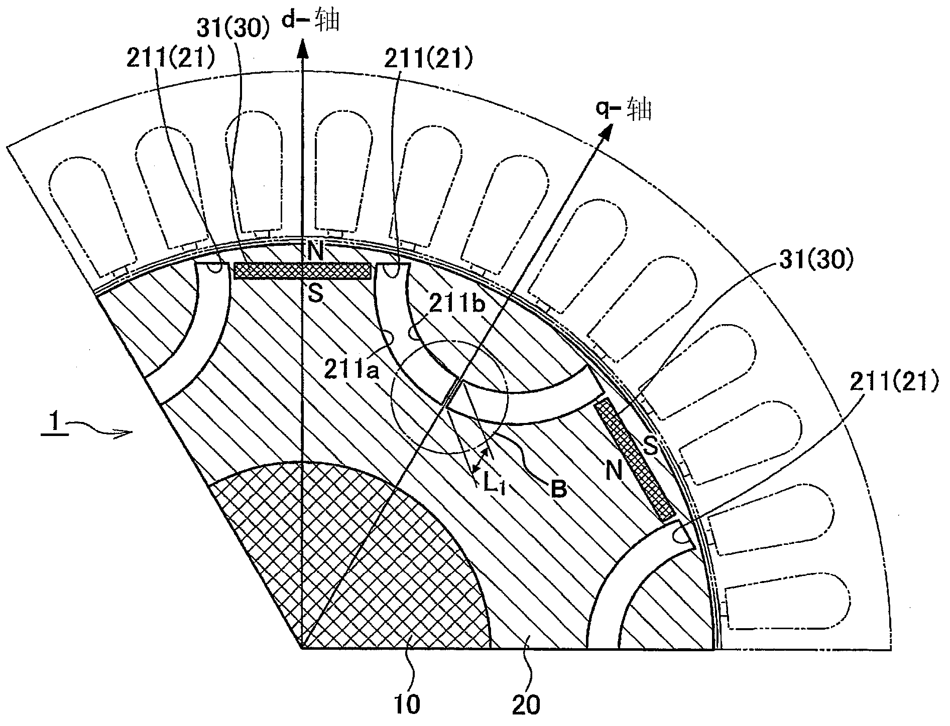
[0025] First refer to Figure 1A , illustrating a partial transverse cross-sectional view of a part of the rotor of a rotary electric machine according to the first embodiment, in a section taken along a section line lying in a plane perpendicular to the axis of the rotor shaft, and Figure 1A 1 / 3 (120 degrees) of the full circumference of the rotor is shown.

[0026] Figure 1B yes Figure 1A A magnified view of part B of , and figure 2 is included Figure 1A A full cross-sectional view of this part is shown in . The rotary electric machine rotor 1 in this example has a rotor shaft 10 , a rotor core 20 and a set 30 of permanent magnets...


PUM


Abstract

A rotary electric machine rotor is provided with a rotor shaft (10), a rotor core (20), and a group (30) of permanent magnets (31). The rotor core (20) includes a group (21) of flux barriers (211) arranged at intervals. At least one of the flux barriers (211) includes at least one bridge (212) joining an inner edge (21 Ia) and an outer edge (21 Ib) of that flux barriers (211). The permanent magnets (31) are arranged at the rotor core (20) between the flux barriers (211) as viewed in the cross sectional plane.

Description

technical field [0001] The present invention generally relates to rotors for use in rotary electric machines. More specifically, the present invention relates to rotors including flux barriers configured to reduce or eliminate damage to the rotor core while improving rotational position sensing and output torque. Background technique [0002] In order to reduce the manufacturing cost as well as reduce the unit size of IPM (Inner Permanent Magnet) type rotary motors, sensorless technology has been developed, in which the sensor for detecting the rotational position of the rotor can be omitted. As understood in the art, a sensorless rotor generally refers to a self-sensing type of rotor capable of sensing the rotational position of the rotor without the use of external sensors or sensors added to the rotor. [0003] When the rotor rotates at high speed, a large induced voltage is generated. The position of the permanent magnet on the rotor can be estimated based on the wavef...

Claims


Application Information

Patent Timeline
Patent Type & Authority Applications(China)
IPC IPC(8): H02K1/27
CPCH02K1/246H02K1/276
Inventor 涩川祐一罗伯特·唐纳德·洛伦茨纳提·利姆斯万
Owner NISSAN MOTOR CO LTD
Features
  • R&D
  • Intellectual Property
  • Life Sciences
  • Materials
  • Tech Scout
  • Unparalleled Data Quality
  • Higher Quality Content
  • 60% Fewer Hallucinations
Learn More