Check patentability & draft patents in minutes with Patsnap Eureka AI!

Fixing device for clamping mold and construction method of clamping mold

A fixing device and mold clamping technology, applied in the direction of mold shell/template/work frame, connection parts of mold shell/template/work frame, and on-site preparation of building components, which can solve the problem of uneven material at the boundary of the spraying area , without the problems of load-bearing and low strength, to achieve the effect of fast construction speed, leveling strength, and ensuring construction quality

Active Publication Date: 2015-12-02
ARCHITECTURAL DESIGN & RES INST OF TSINGHUA UNIV +1
View PDF6 Cites 0 Cited by
  • Summary
  • Abstract
  • Description
  • Claims
  • Application Information

AI Technical Summary

Problems solved by technology

[0002] Due to the advantages of reducing the self-weight of the wall, improving the thermal insulation effect of the wall, and increasing the construction speed, wall prefabricated parts such as steel mesh sandwich light panels are used more and more in construction, and many applicable Based on this new building construction method of wall prefabricated parts, in which the concrete layer is formed by spraying concrete on the surface of the wall prefabricated parts, the construction speed can be further improved compared with the support formwork usually used in the past and then poured concrete on site, resulting in The new problem is that the material at the boundary of the sprayed area is often uneven, loose, and low in strength, so it is usually not used for load-bearing. In addition, since the columns and beams still need to be constructed by pouring in situ, the cast-in-place columns and beams are combined with at least one side of spraying to form concrete How to connect the walls of the layers to achieve the required strength is also a new problem to be solved

Method used


Image

  • Fixing device for clamping mold and construction method of clamping mold
  • Fixing device for clamping mold and construction method of clamping mold
  • Fixing device for clamping mold and construction method of clamping mold

Examples


Embodiment Construction

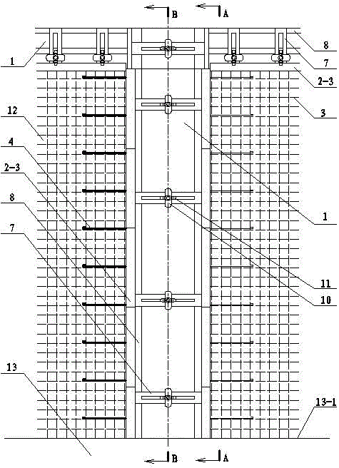
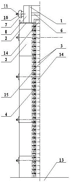
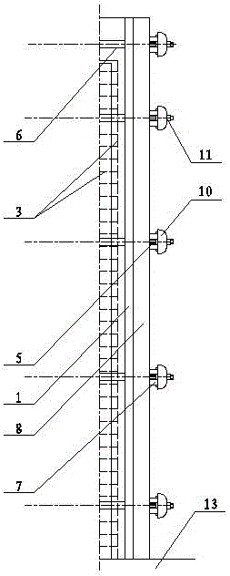
[0028] see Figure 1-5, the present invention provides a clamping mold fixing device, comprising a pair of main formwork 1 and one or more side formworks 2, the main formwork is a rectangular plate, and the side formwork is at least one straight side 2-1 Plates, in the assembled state, the faces of the paired main formworks are arranged in parallel and at intervals, at least one long side edge of at least one main formwork is fixedly connected to the side formwork, and the plate surface of the side formwork is perpendicular to the plate surface of the corresponding main formwork And be attached to the end face of the corresponding long side of the corresponding main template, the straight side extends between the pair of main templates and is parallel to the surface of the main template, when there are multiple side templates set on the long side , the plurality of side templates are continuously and closely connected; the side templates can be a whole board without holes or g...


PUM


Abstract

The invention relates to a sandwich formwork fixing device and a sandwich formwork construction method. The device comprises paired main formworks and one or more side formworks, the main formworks are rectangular slabs, each side formwork is a slab with at least one straight side, and under an assembling state, and the slab surface of each side formwork is perpendicular to the slab surface of the corresponding main formwork and is attached to the end face of a corresponding long side of the corresponding main formwork. The core of the method includes: sandwiching the paired main formworks on two sides of a wall fabricated part, maintaining the paired main formworks and two bedding faces of the wall fabricated part to be arranged parallelly at intervals and fixed, inserting the side formworks at the left, right and upper edges of the exposed wall fabricated part, enabling side formworks and the upper side of an underbeam / foundation to be enclosed all sides, performing formwork pouring for the other side face and columns and beams after concrete sprayed in the enclosed range reaches required strength. A sprayed concrete layer obtained by the device and the method is compact and high in strength and is connected with a cast-in-situ column and a cast-in-suit beam in a high strength manner, and effective matching technology and tools are provided for in-situ spraying construction of sandwiched walls.

Description

technical field [0001] The invention relates to a building formwork and its complete set of fixing tools and a construction method using the tool, mainly suitable for the construction of walls, columns and beams containing sandwich walls, especially suitable for single or double sides of walls Construction constructed by the sprayed concrete method on site. Background technique [0002] Due to the advantages of reducing the self-weight of the wall, improving the thermal insulation effect of the wall, and increasing the construction speed, wall prefabricated parts such as steel mesh sandwich light panels are used more and more in construction, and many applicable Based on this new building construction method of wall prefabricated parts, in which the concrete layer is formed by spraying concrete on the surface of the wall prefabricated parts on site, the construction speed can be further improved compared with the support formwork usually used in the past and then poured conc...

Claims


Application Information

Patent Timeline
Patent Type & Authority Patents(China)
IPC IPC(8): E04G11/08E04G13/02E04G13/04E04G17/065E04G21/00
Inventor 庄惟敏李江波冯葆纯张以超
Owner ARCHITECTURAL DESIGN & RES INST OF TSINGHUA UNIV
Features
  • R&D
  • Intellectual Property
  • Life Sciences
  • Materials
  • Tech Scout
  • Unparalleled Data Quality
  • Higher Quality Content
  • 60% Fewer Hallucinations
Learn More