Continuous flapping-wing aircraft

A flapping-wing aircraft and wing-rotating technology, applied in the field of continuous flapping-wing aircraft, can solve the problems of difficult manufacturing design, high cost, complex structure, etc., and achieve the effect of easy and accurate control of reverse thrust direction and high mechanical efficiency

Active Publication Date: 2013-07-24
关松生
View PDF8 Cites 2 Cited by
  • Summary
  • Abstract
  • Description
  • Claims
  • Application Information

AI Technical Summary

Problems solved by technology

However, the existing flapping wing aircraft has the disadvantages of bulky b

Method used


Image

  • Continuous flapping-wing aircraft
  • Continuous flapping-wing aircraft
  • Continuous flapping-wing aircraft

Examples


Example Embodiment

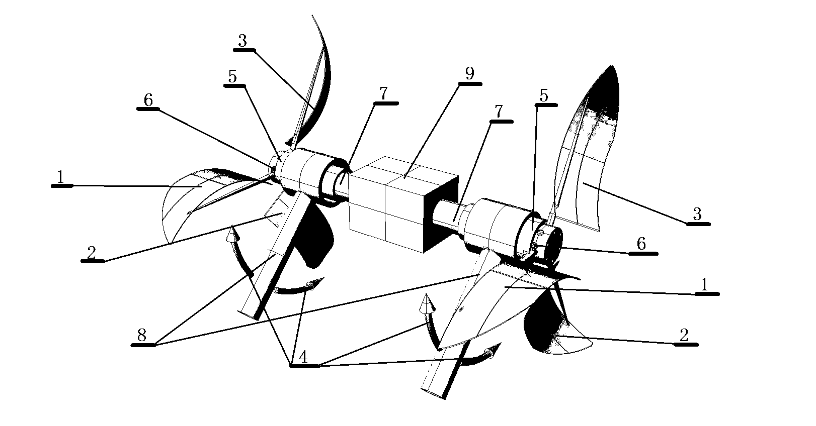
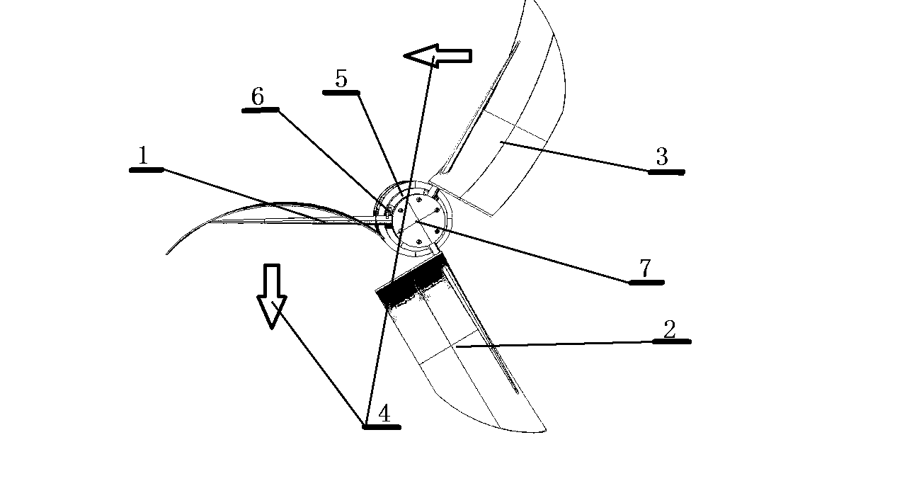
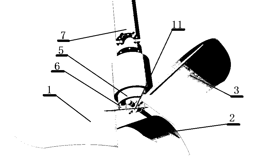
[0009] The structure of the continuous flapping wing aircraft of the present invention will be further described below in conjunction with the accompanying drawings.

[0010] A continuous flapping wing aircraft, characterized in that it is composed of two continuous flapping wing devices connected with an engine 9. The continuous flapping wing device includes a main shaft 7, a control assembly 5, and a first flapping wing 1, a second flapping wing 2, and a second flapping wing. The three-pointed star-shaped through-coaxial device 11 is formed by connecting the rotating wing shafts of the three flapping wings 3; two continuous flapping wings are installed on both sides of the engine 9, and the main shafts 7 of the two continuous flapping wings are respectively installed on the engine 9 The main shaft; the control assembly 5 is composed of the convex portion 12, the concave portion 13, and the control rod 8 are connected into one body. The control assembly 5 is sleeved on the main s...


PUM


Abstract

The invention discloses a continuous flapping-wing aircraft. The continuous flapping-wing aircraft is composed of two continuous wing flapping machines and an engine, wherein the core component of each continuous wing flapping machine is a trifurcate star-like central coaxial connector composed of a first flapping wing, a second flapping wing and a third flapping wing, wing rotating shafts of which are distributed in a trifurcate star-like shape in a same plane and the axial leads of which are crossed at a same central point. The aircraft provided by the invention generates lift force, forwarding force or backward force by using the three flapping wings to continuously flap air, and has the advantages of being high in mechanical efficiency, continuous and stable in operation, quiet, easy and accurate to control a reverse thrust direction.

Description

technical field [0001] The invention is a continuous flapping-wing aircraft which has three flapping wings to beat the air continuously to generate lift and adjust the direction of the lift, which is to change the forward or backward force. Background technique [0002] The orthopter aircraft refers to an aircraft that generates lift and forward force through the active movement of the wings like a bird, also known as the thopter. The advantage of flapping-wing flight is that compared with traditional fixed-wing and rotary-wing aircraft, the main feature of the flapping-wing aircraft is that it integrates lift, hover, propulsion, and control functions into the flapping-wing system, which can fly far and wide with very little energy. Long-distance flight, high maneuverability, low noise, no need for special take-off and landing sites, etc. But the existing flapping-wing aircraft has the disadvantages of heavy body, complex structure, difficult manufacture and design, and hig...

Claims


Application Information

Patent Timeline
IPC IPC(8): B64C33/00
Inventor 关松生
Owner 关松生
Why Eureka
Try Eureka