Method for controlling focus rotation by utilizing orthogonal polarized beam

A technology of beam control and orthogonal lines, applied in the field of applied optics, can solve problems such as large size, unfavorable super-resolution microscopic imaging, elliptical spot rotation angle error, etc., to achieve the effect of increasing applicability and usability

Inactive Publication Date: 2013-07-31
UNIV OF SHANGHAI FOR SCI & TECH
View PDF4 Cites 6 Cited by
  • Summary
  • Abstract
  • Description
  • Claims
  • Application Information

AI Technical Summary

Problems solved by technology

If a circularly polarized beam is used for focusing, the spot shape is circular, but its size is larger than that of linearly polarized light, which is not conducive to the realization of super-resolution microscopy imaging
The study found that the focused spot size of radially polarized light is smaller than that of linearly polarized light, and the wavefront phase modulation of azimuthally polarized light is performed through a vortex phase plate with a topology of 1. The focused spot size is smaller than that of radially polarized light. Smaller, but because it is difficult to generate these two kinds of non-uniformly polarized beams, and the output beams of general commercial lasers are linearly polarized light, so the use of non-uniformly polarized beams as a method to achieve super-resolution has not been widely used
Recently, Seller et al. used linearly polarized light with a wavelength of 1580nm as the incident light. After bein

Method used


Image

  • Method for controlling focus rotation by utilizing orthogonal polarized beam
  • Method for controlling focus rotation by utilizing orthogonal polarized beam

Examples


Example Embodiment

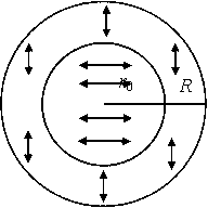
[0018] Based on a single objective lens focusing optical system, when linearly polarized light is focused by a high numerical aperture objective lens, the larger the numerical aperture of the objective lens, the greater the influence of the vector characteristics of the light wave on the light intensity distribution in the focal area, so the focused spot becomes an ellipse In the past, the rotation of the elliptical spot can only be achieved by artificially rotating the half-wave plate. The present invention adopts an orthogonal linearly polarized beam as the incident light, wherein the beam is divided into two parts, one part is the inner ring beam, and the other part is the outer ring beam. Beams, the inner and outer ring beams are concentrically distributed, and the polarization direction of the inner ring linearly polarized light is perpendicular to the polarization direction of the outer ring linearly polarized light. Ring radius, the elliptical focal point rotates around ...


PUM


Abstract

The invention relates to a method for controlling the focus rotation by utilizing an orthogonal polarized beam. The method is characterized in that an orthogonal polarized beam is used as the incidence light, wherein the beam is divided into two parts, one part of the beam is an inner ring beam, the other part of the beam is an outer ring beam, the inner ring beam and the outer ring beam are concentrically distributed, a polarization direction of the inner ring polarized light is vertical to that of the outer ring polarized light, a light spot which is formed by focusing the orthogonal polarized beam through a high-numerical-value aperture objective lens is of an elliptic shape, and the elliptic focus is rotated with the geometric focus as a center by adjusting the inner ring radius and the outer ring radius. Due to the method, the manual rotation of a half wave plate can be avoided, the rotation of the elliptic light spot can be realized, the shape of the orthogonal polarized light focus light spot is identical to that of the linear polarized light focus light spot, the deformation is avoided, the orthogonal beam is easy to produce, the applicability of the method is improved, and the flexibility and manipulability of an experiment also can be improved.

Description

technical field [0001] The invention relates to an applied optical technology, in particular to a method for controlling focus rotation by using orthogonal linearly polarized light beams. Background technique [0002] The light intensity distribution in the focal area has been a research hotspot because its nature greatly affects the performance of the optical system. With the increase of the numerical aperture of the objective lens, due to the increasing influence of the vector characteristics of the beam, it presents special properties in the focal area, and has been widely used in optical information storage, optical microscopy, lithography, laser processing, and optical micromanipulation. , super-resolution, light-matter interaction and other optical systems. [0003] In the study of super-resolution, how to obtain a circularly symmetrical spot with a small size is a difficult research point. In 1959, Wolf et al. found that the spot shape of linearly polarized light un...

Claims


Application Information

Patent Timeline
IPC IPC(8): G02B27/28
Inventor 郭汉明翁晓羽王小亚谭志华庄松林
Owner UNIV OF SHANGHAI FOR SCI & TECH
Why Eureka
Try Eureka