Fuel distributor for gasoline and natural gas

A fuel distributor and fuel distribution technology, which is applied in low-pressure fuel injection, low-pressure fuel injection, fuel injection devices, etc., can solve the problems of increased assembly time and increased number of parts, and achieve reduced installation space, improved layout, and shortened assembly the effect of time

Active Publication Date: 2013-08-14
ROBERT BOSCH GMBH
View PDF5 Cites 3 Cited by
  • Summary
  • Abstract
  • Description
  • Claims
  • Application Information

AI Technical Summary

Problems solved by technology

With respect to gasoline-only operation, the number of components thus increases significantly and assembly times increase according

Method used


Image

  • Fuel distributor for gasoline and natural gas

Examples


Example Embodiment

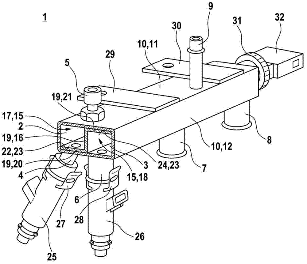
[0014] figure 1 The fuel injector 1 corresponding to the embodiment of the present invention is shown in a simplified schematic perspective view. The fuel distributor 1 can be used especially as a combined fuel distribution pipe of a fuel injection system of a compressed external ignition internal combustion engine. The fuel distributor 1 has a first fuel distribution device 2 and a second fuel distribution device 3. Here, the first fuel distribution device 2 is used to distribute natural gas to a plurality of connection points 4, which are figure 1 Shown in connection point 4. The first fuel distribution device 2 also has a connection point 5 configured as an inlet for natural gas. Here, compressed natural gas is preferably used as natural gas. The second fuel distribution device 3 is used to distribute gasoline to a plurality of connection points 6, 7 and 8 of the second fuel distribution device. Furthermore, the second fuel distribution device 3 has a connection point 9...


PUM


Abstract

The invention relates to a fuel distributor (1) in particular serving as a combined fuel distribution rail for fuel injection systems of mixture-compressing, spark-ignited internal combustion engines, comprising a first fuel distributor piece (2) for distributing natural gas to a plurality of connection points (4) of the first fuel distributor piece (2), and a second fuel distributor piece (3) for distributing gasoline to a plurality of connection points (6, 7, 8) of the second fuel distributor piece (3). The first fuel distributor piece (2) and the second fuel distributor piece (3) are thereby integrated in a common housing (10). The result is a compact design of the fuel distributor (1), whereby the required installation space, the number of individual assembly parts, and the assembly times can be reduced.

Description

technical field [0001] The invention relates to a fuel distributor, in particular a combined fuel distributor platen for a fuel injection system of a hybrid compression externally ignited internal combustion engine. Background technique [0002] Hybrid compression externally ignited internal combustion engines can be adapted to run on gasoline and natural gas. Of course, different fuel injection systems with separate injection valves are required here for the petrol supply and the natural gas supply. The injection valves for gasoline injection can be interconnected via fuel distributors. Correspondingly, the injection valves for natural gas injection can also be connected to one another via further fuel distributors. With regard to gasoline-only operation, the number of components is thus significantly increased and the assembly time correspondingly increased. Furthermore, additional installation space is required in order to install all these components exclusively on th...

Claims


Application Information

Patent Timeline
IPC IPC(8): F02M43/00F02M63/02F02M69/46
CPCF02M63/029F02M69/465F02M43/00
Inventor F·赖特尔H·基施纳
Owner ROBERT BOSCH GMBH
Why Eureka
Try Eureka