Temperature-compensated current transformer based on fiber grating and magnetostrictive material and its current detection method
A technology of magnetostrictive materials and current transformers, applied in the field of transformers, can solve problems such as the influence of current and temperature, and achieve the effect of eliminating the influence of temperature
- Summary
- Abstract
- Description
- Claims
- Application Information
AI Technical Summary
Problems solved by technology
Method used
Image

Examples
specific Embodiment approach 1
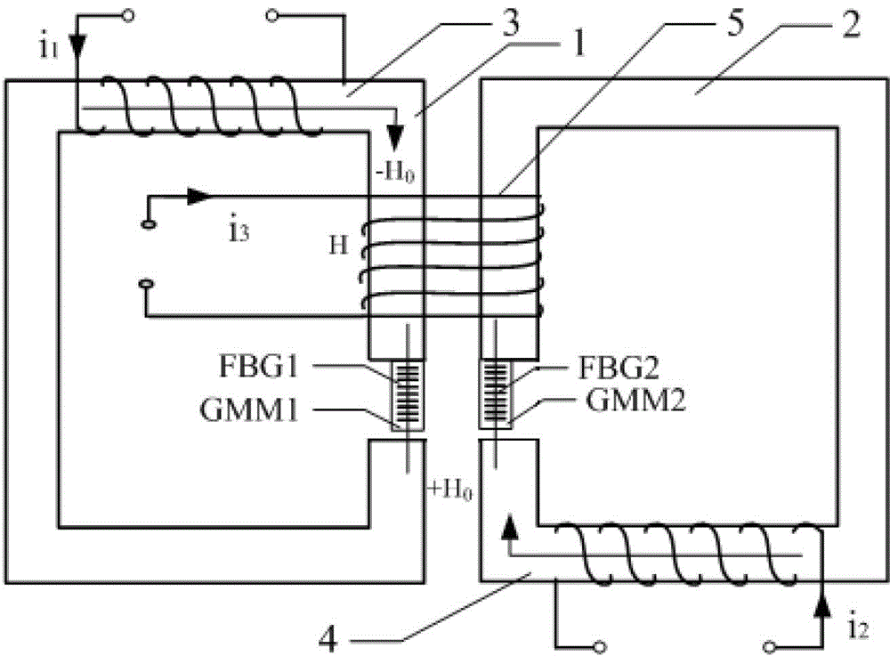
[0020] Specific implementation mode one: see figure 1 Describe this embodiment mode, the temperature-compensated current transformer based on fiber grating and magnetostrictive material described in this embodiment mode, it includes a first rectangular annular iron core 1, a second rectangular annular iron core 2, a first rectangular annular iron core The magnetostrictive device GMM1, the second magnetostrictive device GMM2, the first sensing probe FBG1, the second sensing probe FBG2, the first bias current solenoid 3, the second bias current solenoid 4 and the Current solenoid 5, the structure and shape of the first rectangular annular iron core 1 and the second rectangular annular iron core 2 are all the same, and the first rectangular annular iron core 1 and the second rectangular annular iron core 2 are mirror images Symmetrically arranged, the materials of the first magnetostrictive device GMM1 and the second magnetostrictive device GMM2 are the same, the materials and ce...
specific Embodiment approach 2
[0024] Embodiment 2: This embodiment is a further limitation of the temperature-compensable current transformer based on fiber grating and magnetostrictive material described in Embodiment 1. The first sensing probe FBG1 and the second sensing probe The probe FBG2 is a fiber grating.
specific Embodiment approach 3
[0025] Specific implementation mode three: see Figure 8 Describe this embodiment, the current detection method of the temperature-compensated current transformer based on fiber Bragg grating and magnetostrictive material:
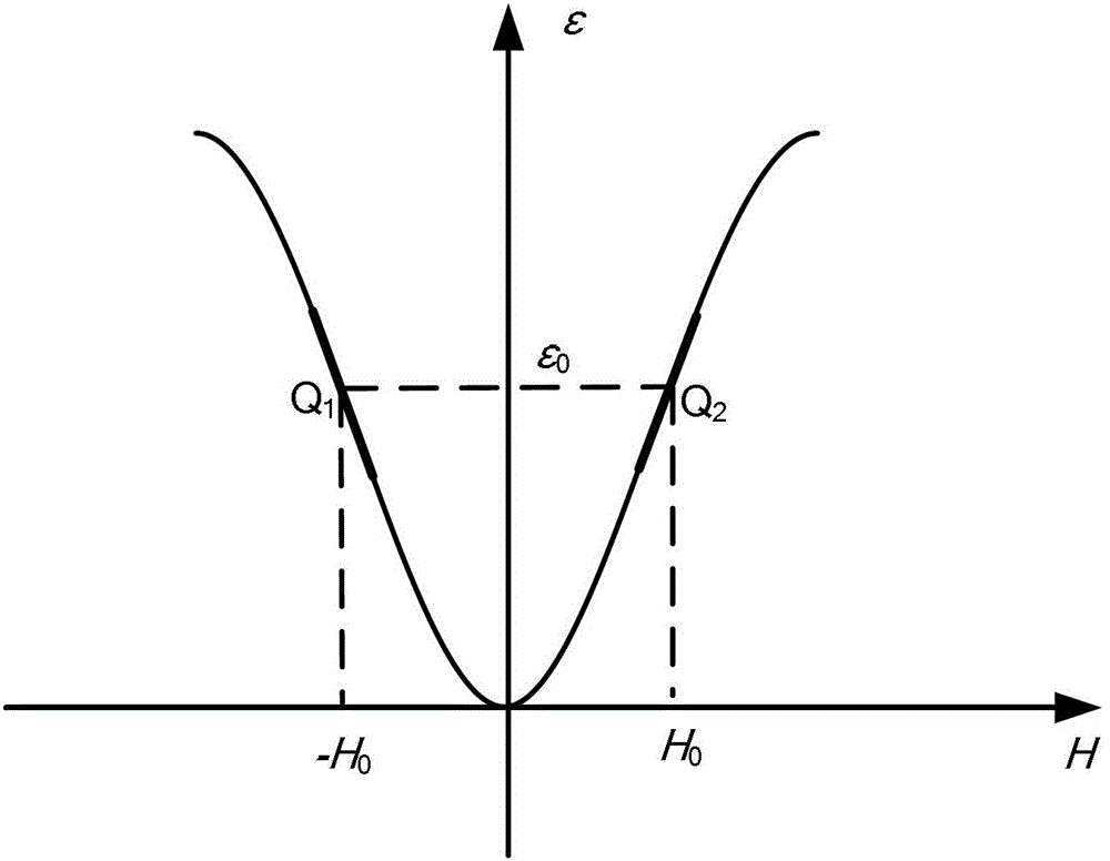
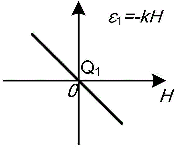
[0026] Step 1: Apply bias current i to the first bias current solenoid 3 1 , add bias current i to the second bias current solenoid 4 2 , making the magnetic field generated at the first rectangular annular core place and the second rectangular annular iron core place have the same magnitude and opposite directions, so that the first magnetostrictive device GMM1 and the second magnetostrictive device GMM2 generate Radial strain ε 0 , at this time the corresponding center wavelengths of the first sensing probe FBG1 and the second sensing probe FBG2 are λ 0 ;
[0027] Step 2: Add the current i to be measured to the current solenoid 5 to be measured 3 , so that the strains of the first magnetostrictive device GMM1 and the second magnetostrictive device G...
PUM
 Abstract
Description
Claims
Application Information
 - R&D
- Intellectual Property
- Life Sciences
- Materials
- Tech Scout
- Unparalleled Data Quality
- Higher Quality Content
- 60% Fewer Hallucinations
Browse by: Latest US Patents, China's latest patents, Technical Efficacy Thesaurus, Application Domain, Technology Topic, Popular Technical Reports.
© 2025 PatSnap. All rights reserved.Legal|Privacy policy|Modern Slavery Act Transparency Statement|Sitemap|About US| Contact US: help@patsnap.com